Showing posts with label charger. Show all posts
Showing posts with label charger. Show all posts
Friday, November 4, 2016
Nokia C2 06 Charger Not Supported Problem Solution Ways
Nokia C2 06 Charger Not Supported Problem Solution Ways
Plug in Charging pin into charging jack of Nokia C2-06 and if it shows an indication message Charger Not Supported it can be due to these few parts that are given bellow in diagram.So after disassemble of Nokia C2-06 clean these parts and area with electronics cleaner.
NOKIA 5230 KEYPAD IC JUMPER KEYPAD SOLUTION

Apply hot air and make it dry.Resold these parts indicated with red lines in above diagram to solve Charger Not Supported in Nokia C2-06
You can take these parts from other models of nokia also to solve charging problem in nokia C2-06
for more detail and new tips and tricks about cellphone service problem keep visiting this page we will update cellphone service diagrams timely with new cellphone diagrams.some related post are also given bellow you can read them also for more information about cellphone.
NOKIA 5230 KEYPAD IC JUMPER KEYPAD SOLUTION
Apply hot air and make it dry.Resold these parts indicated with red lines in above diagram to solve Charger Not Supported in Nokia C2-06
You can take these parts from other models of nokia also to solve charging problem in nokia C2-06
for more detail and new tips and tricks about cellphone service problem keep visiting this page we will update cellphone service diagrams timely with new cellphone diagrams.some related post are also given bellow you can read them also for more information about cellphone.
Available link for download
Tuesday, November 1, 2016
Selecting a Charger for Li Ion Battery
Selecting a Charger for Li Ion Battery
In this discussion we try to learn the right procedure for selecting a charger for a Li-ion battery. The question was raised by Mr. Akshay.
The Question
Hi Sir,
The Question
Hi Sir,
I have a 5000mAh Li-ion battery. Can i select a charger for my Li-ion battery having the following specifications, the product is available on ebay?
I will be thankful if you can help me with a better option or alternate options over this.
Thanks & Regards,
Akshay G. Anarse

Specifications of the Li-ion Battery charger
Just because you can Charge your Li-ion battery optimally, a Li-Ion charger would need 5V mini from a PC USB source, in order to ensure a direct charging of the battery from the PC.
RED led illumination indicates charging mode, while the BLUE Led glows as soon as the battery is Full.
Module Specifications: non-isolated module with Li-ion/Li-Po protection chip.
Size: 25x19mm
Color: As shown in the ebay picture
Maximum current charging Temperature: 30 c
Input voltage: 5V via Micro usb or from any external 4.5V -5.5V DC power supply.
Output voltage for charging the battery to full level : 4.2V
Output current: 1A, and self-adjusting as per the battery mAH specs
Charging Method: CCCV (Constant Current-Constant Voltage)
Protection Chip included: S 8205A
Operating Temperature for this module is as per the Industrial grade (-10 to +85 )
My Reply
Hi Akshay,
Your Li-ion Battery is rated at 5000mAH, so charging it at a 1 amp rate could cause a slow charging of the battery, and could take many hours, therefore selecting the charger for your Li-ion battery is OK, but will have this drawback.
In order to charge your battery at a faster rate, a preferable rate would be 3 amp, higher charging rates up to 5 amps could be tried but that would cause some heating of the battery and therefore might demand a temperature controlled circuit.
A fan cooling could be used for keeping the heat of the battery under control so that the battery is able to charge quickly at a 1C rate.
Here "C" refers to the AH rating of the battery, therefore 1C signifies charging of the Li-ion at its full 5 amp rate.
Instead of going through the hassles of selecting a charger for a Li-ion battery from the market the unit could be built and used at home by following the instructions as explained in this Li-ion battery charger circuit with auto cut off
Available link for download
Wednesday, October 19, 2016

Monday, October 17, 2016
SOLAR BASED MOBILE CHARGER FOR RURAL AREAS WITH BATTERY VOLTAGE ANALYZER
SOLAR BASED MOBILE CHARGER FOR RURAL AREAS WITH BATTERY VOLTAGE ANALYZER
ABSTRACT
With the existing push in the direction of sustainable, clean sources of power, it is no surprise that solar power has become one of the most popular alternative energy sources. Free and available everywhere, the power of the sun can be employed to power everything like cell phones and MP3 player. The suns energy is usually harvested through solar panels that are made up of photovoltaic cells. These cells can convert the suns power into electricity that can be used for a number of purposes. For private use, a handheld solar hybrid charger can be employed to recharge little device for instance a MP3 player, a cell phone, or a camera.
A normal PN junction diode is used for unidirectional flow of charge current. The output of the solar panel depends on the intensity of the solar light. Use of embedded technology makes this system efficient and reliable. Micro controller (ATMega8 / 168 / 328) allows dynamic and faster control. Liquid crystal display (LCD) makes the system user-friendly. ARDUINO is the heart of the circuit as it controls all the functions.
In this project the usage of solar energy by using solar panels are used .A voltage sampler is interfaced with the system to get the voltage generated on a 16X2 LCD.
An alternative charger circuit is also provided to charge the mobile by house hold general purpose 230V in the absence of the sun light. This charge circuit uses regulated 5V, 750mA power supply. 7805 three terminal voltage regulator is used for voltage regulation. Bridge type full wave rectifier is used to rectify the ac output of secondary of 230/18V step down transformer.

If you want to buy this project, drop email on technofieldsystems@gmail.com
Available link for download
Saturday, October 8, 2016
Opamp Low High Battery Charger Controller Circuit
Opamp Low High Battery Charger Controller Circuit
The post discusses a two opamp low high battery charger controller circuit which is not only accurate with its features but also allows a hassle free and quick setting up of its high/low cut-off threshold limits. The idea was requested by Mr. Mamdouh.
The Request
Hi Mr Swagatam,
Ive got the idea, please bear with me, because Im new to circuits design. i actually thought about using opamps to create the circuit that i need, so that makes me feel better i was heading in the right direction.
However, how can i upgrade this smart emergency light circuit to operate on 26-30 volts and 3 amps. Ill be using a dc to dc voltage booster and steady current between the battery and this circuit, as the battery wont be able to supply the required voltage.
so, Im not sure if this circuit will still remain to operates with the voltage booster between the battery and the circuit. also, i will have another voltage booster to be connected the main power adapter as the adapter will only produce 19v and i need 26-30 volts. Im kinda lost with this part because i need circuit to:
1) as soon as i connect the external power automatically it will disconnect the battery and supply the system, in the mean while charging the battery.
2) overcharging protection ( which included in the above design).
3) battery low and full charging indicates (which included in the above design).
4) also i dont know what is the formula to help how to determine the voltage required across my battery to charge it with( battery will be extracted of old laptops.total will be 22V with 6 apms at no load)
5) also, i don,t know the formula to indicate how long my battery will last, and how to calculate the time if i want a battery to last me two hours.
Also, the cpu fan will supplied by the system too.
it would be great too to add the option of a dimmer, my original plane was to vary between 26-30 v not need much more than that.
its a flash light design but using higher wattage LED.
Im sorry for those many questions, but im trying to get help and improve my skills in designing as im very new to electronics world.

The Design
In all of my previous battery charger controller circuits I have used a single opamp for executing the full charge auto cut-off, and have employed a hysteresis resistor for enabling the low level charging switch ON for the connected battery.
However calculating this hysteresis resistor correctly for achieving the precise low level restoration becomes slightly difficult and requires some trial and error effort which can be time consuming.
In the above proposed opamp low high battery charger controller circuit two opamp comparator are incorporated instead of one which simplifies the set up procedures and relieves the user from the long procedures.
Referring to the figure we can see two opamps configured as comparators for sensing the battery voltage and for the required cut-off operations.
Assuming the battery is s 12V battery, the lower A2 opamps 10K preset is set such that its output pin#7 becomes high logic when the battery voltage just crosses the 11V mark (lower discharge threshold), while the upper A1 opamps preset is adjusted such that its output goes high when the battery voltage touches the higher cut off threshold, say at 14.3V.
Therefore at 11V, the A1 output gets positive but due to the presence of the 1N4148 diode this positive stays ineffective and blocked from moving further to the base of the transistor.
The battery continues to charge, until it reaches 14.3V when the upper opamp activates the relay, and stops the charging supply to the battery. The situation is instantly latched due to the inclusion of the feedback resistors across pin#1 and pin#3 of A1. The relay becomes locked in this position with the supply completely cut off for the battery.
The battery now begins slowly discharging via the connected load until it reaches its lower discharge threshold level at 11V when the A2 output is forced to go negative or zero. Now the diode at its output becomes forward biased and quickly breaks the latch by grounding the latching feedback signal between the indicated pins of A1.
With this action the relay is instantly deactivated and restored to its initial N/C position and the charging current yet again begins flowing towards the battery.
This opamp low high battery charger circuit can be used as a DC UPS circuit also for ensuring a continuous supply for the load regardless of the mains presence or absence and for getting an uninterrupted supply through out its usage.
The input charging supply could be acquired from a regulated power supply such as an LM338 constant current variable constant voltage circuit externally.
Answers for other additional questions in the request are as given under:
Formula for calculating full charge cut off limit is:
Battery voltage rating + 20%, for example 20% of 12V is 2.4, so 12 + 2.4 = 14.4V is the full charge cut off voltage for a 12V battery
To know the battery back up time this calculator can be used which gives you the approximate battery back up time.
The Request
Hi Mr Swagatam,
Ive got the idea, please bear with me, because Im new to circuits design. i actually thought about using opamps to create the circuit that i need, so that makes me feel better i was heading in the right direction.
However, how can i upgrade this smart emergency light circuit to operate on 26-30 volts and 3 amps. Ill be using a dc to dc voltage booster and steady current between the battery and this circuit, as the battery wont be able to supply the required voltage.
so, Im not sure if this circuit will still remain to operates with the voltage booster between the battery and the circuit. also, i will have another voltage booster to be connected the main power adapter as the adapter will only produce 19v and i need 26-30 volts. Im kinda lost with this part because i need circuit to:
1) as soon as i connect the external power automatically it will disconnect the battery and supply the system, in the mean while charging the battery.
2) overcharging protection ( which included in the above design).
3) battery low and full charging indicates (which included in the above design).
4) also i dont know what is the formula to help how to determine the voltage required across my battery to charge it with( battery will be extracted of old laptops.total will be 22V with 6 apms at no load)
5) also, i don,t know the formula to indicate how long my battery will last, and how to calculate the time if i want a battery to last me two hours.
Also, the cpu fan will supplied by the system too.
it would be great too to add the option of a dimmer, my original plane was to vary between 26-30 v not need much more than that.
its a flash light design but using higher wattage LED.
Im sorry for those many questions, but im trying to get help and improve my skills in designing as im very new to electronics world.
The Design
In all of my previous battery charger controller circuits I have used a single opamp for executing the full charge auto cut-off, and have employed a hysteresis resistor for enabling the low level charging switch ON for the connected battery.
However calculating this hysteresis resistor correctly for achieving the precise low level restoration becomes slightly difficult and requires some trial and error effort which can be time consuming.
In the above proposed opamp low high battery charger controller circuit two opamp comparator are incorporated instead of one which simplifies the set up procedures and relieves the user from the long procedures.
Referring to the figure we can see two opamps configured as comparators for sensing the battery voltage and for the required cut-off operations.
Assuming the battery is s 12V battery, the lower A2 opamps 10K preset is set such that its output pin#7 becomes high logic when the battery voltage just crosses the 11V mark (lower discharge threshold), while the upper A1 opamps preset is adjusted such that its output goes high when the battery voltage touches the higher cut off threshold, say at 14.3V.
Therefore at 11V, the A1 output gets positive but due to the presence of the 1N4148 diode this positive stays ineffective and blocked from moving further to the base of the transistor.
The battery continues to charge, until it reaches 14.3V when the upper opamp activates the relay, and stops the charging supply to the battery. The situation is instantly latched due to the inclusion of the feedback resistors across pin#1 and pin#3 of A1. The relay becomes locked in this position with the supply completely cut off for the battery.
The battery now begins slowly discharging via the connected load until it reaches its lower discharge threshold level at 11V when the A2 output is forced to go negative or zero. Now the diode at its output becomes forward biased and quickly breaks the latch by grounding the latching feedback signal between the indicated pins of A1.
With this action the relay is instantly deactivated and restored to its initial N/C position and the charging current yet again begins flowing towards the battery.
This opamp low high battery charger circuit can be used as a DC UPS circuit also for ensuring a continuous supply for the load regardless of the mains presence or absence and for getting an uninterrupted supply through out its usage.
The input charging supply could be acquired from a regulated power supply such as an LM338 constant current variable constant voltage circuit externally.
Answers for other additional questions in the request are as given under:
Formula for calculating full charge cut off limit is:
Battery voltage rating + 20%, for example 20% of 12V is 2.4, so 12 + 2.4 = 14.4V is the full charge cut off voltage for a 12V battery
To know the battery back up time this calculator can be used which gives you the approximate battery back up time.
Available link for download
Tuesday, September 27, 2016
Solar Charger Circuit using Transistors with Automatic Cut off
Solar Charger Circuit using Transistors with Automatic Cut off
The post details a simple solar charger circuit with automatic cut-off using transistors only. The idea was requested by Mr. Mubarak Idris.
The Request
Please sir can you make me a 12v, 28.8AH lithium ion battery,automatic charge controller using solar panel as a supply, which is 17v at 4.5A at max sun light please sir its urgent thanks in advance, and the charge controller should be able to have over charge protection and low battery cut off and please sir the circuit should be simple to do for beginner without ic or micro controller, please sir the circuit should use relay or bjt transistors as a switch and zener for voltage reference thanks sir hope to hear from you soon! and sorry to say that I am a student.thanks sir!
The Design
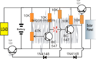
Referring to the above simple solar charger circuit using transistors, the automatic cut off for the full charge charge level and the lower level is done through a couple of BJTs configured as comparators.
Recall the earlier low battery indicator circuit using transistors, where the low battery level was indicated using just two transistors and a few other passive components.
Here we employ an identical design for the sensing of the battery levels and for enforcing the required switching of the battery across the solar panel and the connected load.
Lets assume initially we have a partially discharged battery which causes the first BC547 from left to stop conducting (this is set by adjusting the base preset to this threshold limit), and allows the next BC547 to conduct.
When this BC547 conducts it enable the TIP127 to switch ON, which in turn allows the solar panel voltage to reach the battery and begin charging it.
The above situation conversely keeps the TIP122 switched OFF so that the load is unable to operate.
As the battery begins getting charged, the voltage across the supply rails also begin rising until a point where the left side BC547 is just able to conduct, causing the right side BC547 to stop conducting any further.
As soon as this happens, the TIP127 is inhibited from the negative base signals and it gradually stops conducting such that the battery gradually gets cut off from the solar panel voltage.
However, the above situation permits the TIP122 to slowly receive a base biasing trigger and it begins conducting....which ensures that the load now is able to get the required supply for its operations.
The above explained solar charger circuit using transistors and with auto cut-offs can be used for any small scale solar controller applications such as for charging cellphone batteries or other forms of Li-ion batteries safely.
For getting a Regulated Charging Supply
The design can be easily modified for enabling a regulated fixed voltage supply for the battery, as shown below:

The TIP127 configuration in the above design looks incorrect, the correct version should be as indicated in the following diagram:

The Request
Please sir can you make me a 12v, 28.8AH lithium ion battery,automatic charge controller using solar panel as a supply, which is 17v at 4.5A at max sun light please sir its urgent thanks in advance, and the charge controller should be able to have over charge protection and low battery cut off and please sir the circuit should be simple to do for beginner without ic or micro controller, please sir the circuit should use relay or bjt transistors as a switch and zener for voltage reference thanks sir hope to hear from you soon! and sorry to say that I am a student.thanks sir!
The Design
Referring to the above simple solar charger circuit using transistors, the automatic cut off for the full charge charge level and the lower level is done through a couple of BJTs configured as comparators.
Recall the earlier low battery indicator circuit using transistors, where the low battery level was indicated using just two transistors and a few other passive components.
Here we employ an identical design for the sensing of the battery levels and for enforcing the required switching of the battery across the solar panel and the connected load.
Lets assume initially we have a partially discharged battery which causes the first BC547 from left to stop conducting (this is set by adjusting the base preset to this threshold limit), and allows the next BC547 to conduct.
When this BC547 conducts it enable the TIP127 to switch ON, which in turn allows the solar panel voltage to reach the battery and begin charging it.
The above situation conversely keeps the TIP122 switched OFF so that the load is unable to operate.
As the battery begins getting charged, the voltage across the supply rails also begin rising until a point where the left side BC547 is just able to conduct, causing the right side BC547 to stop conducting any further.
As soon as this happens, the TIP127 is inhibited from the negative base signals and it gradually stops conducting such that the battery gradually gets cut off from the solar panel voltage.
However, the above situation permits the TIP122 to slowly receive a base biasing trigger and it begins conducting....which ensures that the load now is able to get the required supply for its operations.
The above explained solar charger circuit using transistors and with auto cut-offs can be used for any small scale solar controller applications such as for charging cellphone batteries or other forms of Li-ion batteries safely.
For getting a Regulated Charging Supply
The design can be easily modified for enabling a regulated fixed voltage supply for the battery, as shown below:
The TIP127 configuration in the above design looks incorrect, the correct version should be as indicated in the following diagram:
Available link for download
Monday, September 12, 2016

Tuesday, September 6, 2016

Subscribe to:
Posts (Atom)