Tuesday, September 27, 2016
Solar Charger Circuit using Transistors with Automatic Cut off
Solar Charger Circuit using Transistors with Automatic Cut off
The post details a simple solar charger circuit with automatic cut-off using transistors only. The idea was requested by Mr. Mubarak Idris.
The Request
Please sir can you make me a 12v, 28.8AH lithium ion battery,automatic charge controller using solar panel as a supply, which is 17v at 4.5A at max sun light please sir its urgent thanks in advance, and the charge controller should be able to have over charge protection and low battery cut off and please sir the circuit should be simple to do for beginner without ic or micro controller, please sir the circuit should use relay or bjt transistors as a switch and zener for voltage reference thanks sir hope to hear from you soon! and sorry to say that I am a student.thanks sir!
The Design
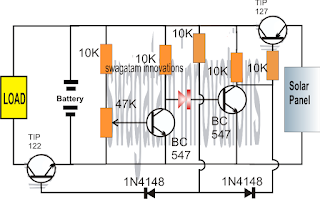
Referring to the above simple solar charger circuit using transistors, the automatic cut off for the full charge charge level and the lower level is done through a couple of BJTs configured as comparators.
Recall the earlier low battery indicator circuit using transistors, where the low battery level was indicated using just two transistors and a few other passive components.
Here we employ an identical design for the sensing of the battery levels and for enforcing the required switching of the battery across the solar panel and the connected load.
Lets assume initially we have a partially discharged battery which causes the first BC547 from left to stop conducting (this is set by adjusting the base preset to this threshold limit), and allows the next BC547 to conduct.
When this BC547 conducts it enable the TIP127 to switch ON, which in turn allows the solar panel voltage to reach the battery and begin charging it.
The above situation conversely keeps the TIP122 switched OFF so that the load is unable to operate.
As the battery begins getting charged, the voltage across the supply rails also begin rising until a point where the left side BC547 is just able to conduct, causing the right side BC547 to stop conducting any further.
As soon as this happens, the TIP127 is inhibited from the negative base signals and it gradually stops conducting such that the battery gradually gets cut off from the solar panel voltage.
However, the above situation permits the TIP122 to slowly receive a base biasing trigger and it begins conducting....which ensures that the load now is able to get the required supply for its operations.
The above explained solar charger circuit using transistors and with auto cut-offs can be used for any small scale solar controller applications such as for charging cellphone batteries or other forms of Li-ion batteries safely.
For getting a Regulated Charging Supply
The design can be easily modified for enabling a regulated fixed voltage supply for the battery, as shown below:

The TIP127 configuration in the above design looks incorrect, the correct version should be as indicated in the following diagram:

The Request
Please sir can you make me a 12v, 28.8AH lithium ion battery,automatic charge controller using solar panel as a supply, which is 17v at 4.5A at max sun light please sir its urgent thanks in advance, and the charge controller should be able to have over charge protection and low battery cut off and please sir the circuit should be simple to do for beginner without ic or micro controller, please sir the circuit should use relay or bjt transistors as a switch and zener for voltage reference thanks sir hope to hear from you soon! and sorry to say that I am a student.thanks sir!
The Design
Referring to the above simple solar charger circuit using transistors, the automatic cut off for the full charge charge level and the lower level is done through a couple of BJTs configured as comparators.
Recall the earlier low battery indicator circuit using transistors, where the low battery level was indicated using just two transistors and a few other passive components.
Here we employ an identical design for the sensing of the battery levels and for enforcing the required switching of the battery across the solar panel and the connected load.
Lets assume initially we have a partially discharged battery which causes the first BC547 from left to stop conducting (this is set by adjusting the base preset to this threshold limit), and allows the next BC547 to conduct.
When this BC547 conducts it enable the TIP127 to switch ON, which in turn allows the solar panel voltage to reach the battery and begin charging it.
The above situation conversely keeps the TIP122 switched OFF so that the load is unable to operate.
As the battery begins getting charged, the voltage across the supply rails also begin rising until a point where the left side BC547 is just able to conduct, causing the right side BC547 to stop conducting any further.
As soon as this happens, the TIP127 is inhibited from the negative base signals and it gradually stops conducting such that the battery gradually gets cut off from the solar panel voltage.
However, the above situation permits the TIP122 to slowly receive a base biasing trigger and it begins conducting....which ensures that the load now is able to get the required supply for its operations.
The above explained solar charger circuit using transistors and with auto cut-offs can be used for any small scale solar controller applications such as for charging cellphone batteries or other forms of Li-ion batteries safely.
For getting a Regulated Charging Supply
The design can be easily modified for enabling a regulated fixed voltage supply for the battery, as shown below:
The TIP127 configuration in the above design looks incorrect, the correct version should be as indicated in the following diagram:
Available link for download