Showing posts with label cut. Show all posts
Showing posts with label cut. Show all posts
Tuesday, September 27, 2016
Solar Charger Circuit using Transistors with Automatic Cut off
Solar Charger Circuit using Transistors with Automatic Cut off
The post details a simple solar charger circuit with automatic cut-off using transistors only. The idea was requested by Mr. Mubarak Idris.
The Request
Please sir can you make me a 12v, 28.8AH lithium ion battery,automatic charge controller using solar panel as a supply, which is 17v at 4.5A at max sun light please sir its urgent thanks in advance, and the charge controller should be able to have over charge protection and low battery cut off and please sir the circuit should be simple to do for beginner without ic or micro controller, please sir the circuit should use relay or bjt transistors as a switch and zener for voltage reference thanks sir hope to hear from you soon! and sorry to say that I am a student.thanks sir!
The Design
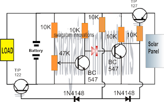
Referring to the above simple solar charger circuit using transistors, the automatic cut off for the full charge charge level and the lower level is done through a couple of BJTs configured as comparators.
Recall the earlier low battery indicator circuit using transistors, where the low battery level was indicated using just two transistors and a few other passive components.
Here we employ an identical design for the sensing of the battery levels and for enforcing the required switching of the battery across the solar panel and the connected load.
Lets assume initially we have a partially discharged battery which causes the first BC547 from left to stop conducting (this is set by adjusting the base preset to this threshold limit), and allows the next BC547 to conduct.
When this BC547 conducts it enable the TIP127 to switch ON, which in turn allows the solar panel voltage to reach the battery and begin charging it.
The above situation conversely keeps the TIP122 switched OFF so that the load is unable to operate.
As the battery begins getting charged, the voltage across the supply rails also begin rising until a point where the left side BC547 is just able to conduct, causing the right side BC547 to stop conducting any further.
As soon as this happens, the TIP127 is inhibited from the negative base signals and it gradually stops conducting such that the battery gradually gets cut off from the solar panel voltage.
However, the above situation permits the TIP122 to slowly receive a base biasing trigger and it begins conducting....which ensures that the load now is able to get the required supply for its operations.
The above explained solar charger circuit using transistors and with auto cut-offs can be used for any small scale solar controller applications such as for charging cellphone batteries or other forms of Li-ion batteries safely.
For getting a Regulated Charging Supply
The design can be easily modified for enabling a regulated fixed voltage supply for the battery, as shown below:

The TIP127 configuration in the above design looks incorrect, the correct version should be as indicated in the following diagram:

The Request
Please sir can you make me a 12v, 28.8AH lithium ion battery,automatic charge controller using solar panel as a supply, which is 17v at 4.5A at max sun light please sir its urgent thanks in advance, and the charge controller should be able to have over charge protection and low battery cut off and please sir the circuit should be simple to do for beginner without ic or micro controller, please sir the circuit should use relay or bjt transistors as a switch and zener for voltage reference thanks sir hope to hear from you soon! and sorry to say that I am a student.thanks sir!
The Design
Referring to the above simple solar charger circuit using transistors, the automatic cut off for the full charge charge level and the lower level is done through a couple of BJTs configured as comparators.
Recall the earlier low battery indicator circuit using transistors, where the low battery level was indicated using just two transistors and a few other passive components.
Here we employ an identical design for the sensing of the battery levels and for enforcing the required switching of the battery across the solar panel and the connected load.
Lets assume initially we have a partially discharged battery which causes the first BC547 from left to stop conducting (this is set by adjusting the base preset to this threshold limit), and allows the next BC547 to conduct.
When this BC547 conducts it enable the TIP127 to switch ON, which in turn allows the solar panel voltage to reach the battery and begin charging it.
The above situation conversely keeps the TIP122 switched OFF so that the load is unable to operate.
As the battery begins getting charged, the voltage across the supply rails also begin rising until a point where the left side BC547 is just able to conduct, causing the right side BC547 to stop conducting any further.
As soon as this happens, the TIP127 is inhibited from the negative base signals and it gradually stops conducting such that the battery gradually gets cut off from the solar panel voltage.
However, the above situation permits the TIP122 to slowly receive a base biasing trigger and it begins conducting....which ensures that the load now is able to get the required supply for its operations.
The above explained solar charger circuit using transistors and with auto cut-offs can be used for any small scale solar controller applications such as for charging cellphone batteries or other forms of Li-ion batteries safely.
For getting a Regulated Charging Supply
The design can be easily modified for enabling a regulated fixed voltage supply for the battery, as shown below:
The TIP127 configuration in the above design looks incorrect, the correct version should be as indicated in the following diagram:
Available link for download

Thursday, September 15, 2016
SERVO CONTROLLED VOLTAGE STABILIZER WITH AUTOMATIC HIGHER AND LOWER CUT OFF
SERVO CONTROLLED VOLTAGE STABILIZER WITH AUTOMATIC HIGHER AND LOWER CUT OFF
ABSTRACT:
This is a stabilizer which constantly monitors the output voltage and controls the variations in the input voltage by movements of a motor. This motor in turn selects the proper output voltage on the variable transformer (variac). This is probably the cheapest power-conditioning product available. It gives reasonably good voltage regulation and is all right where voltage fluctuations are not considerable. However it is not advisable to use it outside big cities where apart from considerable fluctuations in voltage, the power is full of frequency drifts, failures, noise and spikes.
Use of Servo Stabilizer is the only way to control erratic supply voltage conditions. Servo Stabilizer can control all types of loads i.e. inductive, resistive, capacitive loads. Other voltage stabilizers viz. Constant Voltage Transformers or Static Voltage Stabilizers cannot be used in such applications. Servo Stabilizers are available from 1 KVA 1 ph. to 250 KVA 1 ph and 3 KVA 3 ph to 2000 KVA 3 ph. 3 ph. Servo Stabilizers can be for balanced or for unbalanced input voltages. Servo Stabilizer has four major components
- Driver Unit
- Motorized variable voltage auto transformer
- Double-wound Buck Boost / Series transformer
- Servo controlled sensing card (PCB)
After determining Input voltage band and load of customer we design our servo stabilizer to take care of the minimum and maximum voltage fluctuations. While ordering servo stabilizer care should be taken to ensure that servo stabilizer capacity is 20% more than maximum load. In servo stabilizer determine output is determined voltage and the same is set by means of servo controlled sensing card (PCB). Whenever change in output voltage which occurs due to change in Input voltage, the servo controlled sensing card (PCB) gives signal to the motor fitted on variable voltage auto transformer to either increase or decrease the output voltage to achieve the predetermined output voltage.

Available link for download
Subscribe to:
Posts (Atom)