Showing posts with label controller. Show all posts
Showing posts with label controller. Show all posts
Saturday, October 8, 2016
Opamp Low High Battery Charger Controller Circuit
Opamp Low High Battery Charger Controller Circuit
The post discusses a two opamp low high battery charger controller circuit which is not only accurate with its features but also allows a hassle free and quick setting up of its high/low cut-off threshold limits. The idea was requested by Mr. Mamdouh.
The Request
Hi Mr Swagatam,
Ive got the idea, please bear with me, because Im new to circuits design. i actually thought about using opamps to create the circuit that i need, so that makes me feel better i was heading in the right direction.
However, how can i upgrade this smart emergency light circuit to operate on 26-30 volts and 3 amps. Ill be using a dc to dc voltage booster and steady current between the battery and this circuit, as the battery wont be able to supply the required voltage.
so, Im not sure if this circuit will still remain to operates with the voltage booster between the battery and the circuit. also, i will have another voltage booster to be connected the main power adapter as the adapter will only produce 19v and i need 26-30 volts. Im kinda lost with this part because i need circuit to:
1) as soon as i connect the external power automatically it will disconnect the battery and supply the system, in the mean while charging the battery.
2) overcharging protection ( which included in the above design).
3) battery low and full charging indicates (which included in the above design).
4) also i dont know what is the formula to help how to determine the voltage required across my battery to charge it with( battery will be extracted of old laptops.total will be 22V with 6 apms at no load)
5) also, i don,t know the formula to indicate how long my battery will last, and how to calculate the time if i want a battery to last me two hours.
Also, the cpu fan will supplied by the system too.
it would be great too to add the option of a dimmer, my original plane was to vary between 26-30 v not need much more than that.
its a flash light design but using higher wattage LED.
Im sorry for those many questions, but im trying to get help and improve my skills in designing as im very new to electronics world.

The Design
In all of my previous battery charger controller circuits I have used a single opamp for executing the full charge auto cut-off, and have employed a hysteresis resistor for enabling the low level charging switch ON for the connected battery.
However calculating this hysteresis resistor correctly for achieving the precise low level restoration becomes slightly difficult and requires some trial and error effort which can be time consuming.
In the above proposed opamp low high battery charger controller circuit two opamp comparator are incorporated instead of one which simplifies the set up procedures and relieves the user from the long procedures.
Referring to the figure we can see two opamps configured as comparators for sensing the battery voltage and for the required cut-off operations.
Assuming the battery is s 12V battery, the lower A2 opamps 10K preset is set such that its output pin#7 becomes high logic when the battery voltage just crosses the 11V mark (lower discharge threshold), while the upper A1 opamps preset is adjusted such that its output goes high when the battery voltage touches the higher cut off threshold, say at 14.3V.
Therefore at 11V, the A1 output gets positive but due to the presence of the 1N4148 diode this positive stays ineffective and blocked from moving further to the base of the transistor.
The battery continues to charge, until it reaches 14.3V when the upper opamp activates the relay, and stops the charging supply to the battery. The situation is instantly latched due to the inclusion of the feedback resistors across pin#1 and pin#3 of A1. The relay becomes locked in this position with the supply completely cut off for the battery.
The battery now begins slowly discharging via the connected load until it reaches its lower discharge threshold level at 11V when the A2 output is forced to go negative or zero. Now the diode at its output becomes forward biased and quickly breaks the latch by grounding the latching feedback signal between the indicated pins of A1.
With this action the relay is instantly deactivated and restored to its initial N/C position and the charging current yet again begins flowing towards the battery.
This opamp low high battery charger circuit can be used as a DC UPS circuit also for ensuring a continuous supply for the load regardless of the mains presence or absence and for getting an uninterrupted supply through out its usage.
The input charging supply could be acquired from a regulated power supply such as an LM338 constant current variable constant voltage circuit externally.
Answers for other additional questions in the request are as given under:
Formula for calculating full charge cut off limit is:
Battery voltage rating + 20%, for example 20% of 12V is 2.4, so 12 + 2.4 = 14.4V is the full charge cut off voltage for a 12V battery
To know the battery back up time this calculator can be used which gives you the approximate battery back up time.
The Request
Hi Mr Swagatam,
Ive got the idea, please bear with me, because Im new to circuits design. i actually thought about using opamps to create the circuit that i need, so that makes me feel better i was heading in the right direction.
However, how can i upgrade this smart emergency light circuit to operate on 26-30 volts and 3 amps. Ill be using a dc to dc voltage booster and steady current between the battery and this circuit, as the battery wont be able to supply the required voltage.
so, Im not sure if this circuit will still remain to operates with the voltage booster between the battery and the circuit. also, i will have another voltage booster to be connected the main power adapter as the adapter will only produce 19v and i need 26-30 volts. Im kinda lost with this part because i need circuit to:
1) as soon as i connect the external power automatically it will disconnect the battery and supply the system, in the mean while charging the battery.
2) overcharging protection ( which included in the above design).
3) battery low and full charging indicates (which included in the above design).
4) also i dont know what is the formula to help how to determine the voltage required across my battery to charge it with( battery will be extracted of old laptops.total will be 22V with 6 apms at no load)
5) also, i don,t know the formula to indicate how long my battery will last, and how to calculate the time if i want a battery to last me two hours.
Also, the cpu fan will supplied by the system too.
it would be great too to add the option of a dimmer, my original plane was to vary between 26-30 v not need much more than that.
its a flash light design but using higher wattage LED.
Im sorry for those many questions, but im trying to get help and improve my skills in designing as im very new to electronics world.
The Design
In all of my previous battery charger controller circuits I have used a single opamp for executing the full charge auto cut-off, and have employed a hysteresis resistor for enabling the low level charging switch ON for the connected battery.
However calculating this hysteresis resistor correctly for achieving the precise low level restoration becomes slightly difficult and requires some trial and error effort which can be time consuming.
In the above proposed opamp low high battery charger controller circuit two opamp comparator are incorporated instead of one which simplifies the set up procedures and relieves the user from the long procedures.
Referring to the figure we can see two opamps configured as comparators for sensing the battery voltage and for the required cut-off operations.
Assuming the battery is s 12V battery, the lower A2 opamps 10K preset is set such that its output pin#7 becomes high logic when the battery voltage just crosses the 11V mark (lower discharge threshold), while the upper A1 opamps preset is adjusted such that its output goes high when the battery voltage touches the higher cut off threshold, say at 14.3V.
Therefore at 11V, the A1 output gets positive but due to the presence of the 1N4148 diode this positive stays ineffective and blocked from moving further to the base of the transistor.
The battery continues to charge, until it reaches 14.3V when the upper opamp activates the relay, and stops the charging supply to the battery. The situation is instantly latched due to the inclusion of the feedback resistors across pin#1 and pin#3 of A1. The relay becomes locked in this position with the supply completely cut off for the battery.
The battery now begins slowly discharging via the connected load until it reaches its lower discharge threshold level at 11V when the A2 output is forced to go negative or zero. Now the diode at its output becomes forward biased and quickly breaks the latch by grounding the latching feedback signal between the indicated pins of A1.
With this action the relay is instantly deactivated and restored to its initial N/C position and the charging current yet again begins flowing towards the battery.
This opamp low high battery charger circuit can be used as a DC UPS circuit also for ensuring a continuous supply for the load regardless of the mains presence or absence and for getting an uninterrupted supply through out its usage.
The input charging supply could be acquired from a regulated power supply such as an LM338 constant current variable constant voltage circuit externally.
Answers for other additional questions in the request are as given under:
Formula for calculating full charge cut off limit is:
Battery voltage rating + 20%, for example 20% of 12V is 2.4, so 12 + 2.4 = 14.4V is the full charge cut off voltage for a 12V battery
To know the battery back up time this calculator can be used which gives you the approximate battery back up time.
Available link for download

Saturday, October 1, 2016
Synchronous Switch Mode MPPT Battery Charge Controller Circuit
Synchronous Switch Mode MPPT Battery Charge Controller Circuit
The device bq24650 includes an advanced built-in MPPT Synchronous Switch-Mode Battery Charge Controller. It offers a high level of input voltage regulation, which prevents the charging current to the battery each time input voltage drops below a specified amount. Learn More:
Whenever the input is attached with a a solar panel, the supply stabilization loop pulls down the charging amp to ensure that the solar panel is enabled to produce maximum power output.
The bq24650 promises to provide a constant-frequency synchronous PWIVI controller with optimal level of accuracy with current and voltage stabilization, charge preconditioning, charge cut-off, and charging level checking.
The chip charges the battery in 3 discrete levels: pre-conditioning, constant current, and constant voltage.
Charging is is cut-off as soon as the amp level nears the 1/10 of the rapid charging rate. The pre-charge timer is set to be at 30 minutes.
The bq2465O without a manual intervention restarts the charging procedure in case the battery voltage reverts below an internally set limit or reaches a minimum quiescent amp sleep mode while the input voltage goes below the battery voltage.
The device is designed to charge a battery from 2.1V to 26V with VFB internally fixed to a 2.1V feedback point. The charging amp spec is preset internally by fixing a well matched sensing resistor.
The bq24650 can be procured with a 16 pin, 3.5 x 3.5 mm^2 thin QFN option.
 Courtesy: MPPT Synchronous Switch-Mode Battery Charge Controller Circuit
The bq24G50 employs an extremely accurate voltage regulator for the deciding on the charging voltage. The charging voltage is preset by means of a a resistor divider from the battery to ground, with the midpoint hooked up the VFB pin.
The voltage at the VFB pin is clamped to 2.1V, in order to produce the following formula for the level of regulation voltage:
V(batt) = 2.1V x [1 + R2/R1]
where R2 is linked from VFB to the battery and R1 is connected from VFB to GND. Li-Ion, LiFePO4, as well as SMF lead acid batteries are ideally supported battery chemistries.
A majority of over the shelf Li-ion cells can now be effectively charged up to 4.2V/cell. A LiFePO4 battery supports the process of a substantially higher charge and discharge cycles, but the down side is that the the energy density is not too good. The recognized cell voltage is 3.6V.
The charge profile of the two cells Li-Ion and LiFePO4 is preconditioning, constant current, and constant voltage. For an effective charge/discharge life, the end-of-charge voltage limit may possibly be cut down to 4.1V/cell however it‘s energy density could become a lot lower compared to the Li-based chemical specification, lead acid continues to be much preferred battery because of its reduced production expenses as well as rapid discharge cycles.
The common voltage threshold is from 2.3V to 2.45V. After the battery is seen to be completely topped up, a float or trickle charge becomes mandatory in order make up for the self-discharge. The trickle charge threshold is 100mV-200mV below the constant voltage point.
A solar panel may have an exclusive level on the V-I or V-P curve, popularly known as the Maximum Power Point (MPP), wherein the complete photovoltaic (PV) system relies with optimum efficiency and generates the required maximum output power.
The constant voltage algorithm is the most easy Maximum Power Point Tracking (MPPT) option available. The bq2465O automatically shuts down the charging amp such that the maximum power point is is enabled for producing maximum efficiency.
The chip bq2465O incorporates a "SLEEP" comparator to identify the means of supply voltage on the VCC pin, because of the fact that VCC may be terminated both from a battery or an external AC/DC adapter unit.
If the VCC voltage is more significant the SRN voltage, and the additional criteria are fulfilled for the charging procedures, the bq2465O subsequently begins making an attempt to charge a connected battery (please see the Enabling and Disabling Charging section).
lf SRN voltage is higher with respect to the VCC, symbolizing that a battery is the source from where the power is being acquired, the bq2465O is enabled for a lower quiescent current ( <15uA) SLEEP mode to prevent amperage leakage from the battery.
lf VCC is below the UVLO limit, the IC is cut-off, after which VREF LDO is switched off.
The following concerned aspects need to be ensured before the charging process of the proposed MPPT Synchronous Switch-Mode Battery Charge Controller Circuit is initialized:
• Charging process is enabled (MPPSET > 175mV)
• The unit is not in Under-Voltage-Lock-Out (UVLO) functionality and VCC is above the VCCLOWV limit
• The IC is not in SLEEP functionality (i.e. VCC > SRN)
• VCC voltage is below the AC over-voltage limit (VCC < VACOV)
• 30ms time lapse is fulfilled after the first power-up
• REGN LDO and VREF LDO voltages are fixed at the specified junctures
• Thermal Shut (TSHUT) is not initialized
- TS bad is not identified
Any one of the following technical issues may inhibit the proceeding charging of the battery:
• Charging is is deactivated (MPPSET < 75mV)
• Adapter input is disconnected, provoking the IC to get into a VCCLOWV or SLEEP functionality
• Adapter input voltage is below the 100mV above battery mark
• Adapter is rated at higher voltage
• REGN or VREF LDO voltage is not as per the specs
• TSHUT IC warmth limit is identified
• TS voltage happens to move out of the specified range which may indicate that the battery temperature is extremely hot or alternatively much cooler
Self-Triggered In-built SOFT-START CHARGER CURRENT
The charger by irself soft-starts the charger power regulation current each time the charger moves into the fast-charge to establish that there is absolutely no overshoot or stressful conditions on the externally connected capacitors or the power converter.
The soft-start is featured with of stepping-up the chaging stabilization amp into eight uniformly executed operational steps next to the prefixed charging current level. All the assigned steps carry on for around 1.6ms, for a specified Up period of 13ms. Not a single external parts are called for enabling the discussed operational
function.
The synchronous buck PWM converter employs a predetermined frequency voltage mode with feed-forvvard control strategy.
A version III compensation configuration lets the system to incorporate ceramic capacitors at the output stage of the converter. The compensation
input stage is associated internally between the feedback output (FBO) along with an error amplifier input (EAI).
The feedback compensation stage is rigged between the error amplifier input (EAI) and error amplifier output (EAO). The LC output filter stage needs to be determined to enable a resonant frequency of around 12 kHz - 17 kHz for the device, for which the resonant frequency, fo, is formulated as:
fo = 1 / 2 ? ?LoCo
An integrated saw-tooth ramp is allowed to compare the internal EAO error control input to alter the duty-cycle of the converter.
The ramp amplitude is 7% of the input adapter voltage enabling it to be permanently and completely proportional to the input supply of the adapter voltage.
This cancels away any sort of loop gain alterations on account of a variation in the input voltage and simplifies the loop compensation procedures. The ramp is balanced out by 300mV so that a zero percent duty-cycIe is achieved when the EAO signal is below the ramp.
The EAO signal is likewise qualified to outnumber the saw-tooth ramp signal with a purpose to achieve a 100% duty cycIe PWM demand.
Built in gate drive logic makes it possible accomplishing 99.98% duty-cycle at the same time confirming the
N-channel upper device consistently carries as much as necessary voltage to always be 100 % on.
In the event the BTST pin to PH pin voltage reduces below 4.2V for longer than three intervals, in that case the high-side n-channeI power MOSFET is switched off while the low-side n-channe| power MOSFET is triggered to draw the PH node down and charge-up the BTST capacitor.
After that the high-side driver normalizes to 100% duty-cycle procedure until the (BTST-PH) voltage is observed to decline low yet again, on account of outflow current depleting the BTST capacitor below 4.2 V, as well as reset pulse is reissued.
The predetermined frequency oscillator maintains rigid command over the switching frequency under most circumstances of input voltage, battery voltage, charge current, and temperature, simplifying output filter layout and retaining it away from the audible disturbances state.
Whenever the input is attached with a a solar panel, the supply stabilization loop pulls down the charging amp to ensure that the solar panel is enabled to produce maximum power output.
The bq24650 promises to provide a constant-frequency synchronous PWIVI controller with optimal level of accuracy with current and voltage stabilization, charge preconditioning, charge cut-off, and charging level checking.
The chip charges the battery in 3 discrete levels: pre-conditioning, constant current, and constant voltage.
Charging is is cut-off as soon as the amp level nears the 1/10 of the rapid charging rate. The pre-charge timer is set to be at 30 minutes.
The bq2465O without a manual intervention restarts the charging procedure in case the battery voltage reverts below an internally set limit or reaches a minimum quiescent amp sleep mode while the input voltage goes below the battery voltage.
The device is designed to charge a battery from 2.1V to 26V with VFB internally fixed to a 2.1V feedback point. The charging amp spec is preset internally by fixing a well matched sensing resistor.
The bq24650 can be procured with a 16 pin, 3.5 x 3.5 mm^2 thin QFN option.
BATTERY VOLTAGE REGULATION
The bq24G50 employs an extremely accurate voltage regulator for the deciding on the charging voltage. The charging voltage is preset by means of a a resistor divider from the battery to ground, with the midpoint hooked up the VFB pin.
The voltage at the VFB pin is clamped to 2.1V, in order to produce the following formula for the level of regulation voltage:
V(batt) = 2.1V x [1 + R2/R1]
where R2 is linked from VFB to the battery and R1 is connected from VFB to GND. Li-Ion, LiFePO4, as well as SMF lead acid batteries are ideally supported battery chemistries.
A majority of over the shelf Li-ion cells can now be effectively charged up to 4.2V/cell. A LiFePO4 battery supports the process of a substantially higher charge and discharge cycles, but the down side is that the the energy density is not too good. The recognized cell voltage is 3.6V.
The charge profile of the two cells Li-Ion and LiFePO4 is preconditioning, constant current, and constant voltage. For an effective charge/discharge life, the end-of-charge voltage limit may possibly be cut down to 4.1V/cell however it‘s energy density could become a lot lower compared to the Li-based chemical specification, lead acid continues to be much preferred battery because of its reduced production expenses as well as rapid discharge cycles.
The common voltage threshold is from 2.3V to 2.45V. After the battery is seen to be completely topped up, a float or trickle charge becomes mandatory in order make up for the self-discharge. The trickle charge threshold is 100mV-200mV below the constant voltage point.
INPUT VOLTAGE REGULATION
A solar panel may have an exclusive level on the V-I or V-P curve, popularly known as the Maximum Power Point (MPP), wherein the complete photovoltaic (PV) system relies with optimum efficiency and generates the required maximum output power.
The constant voltage algorithm is the most easy Maximum Power Point Tracking (MPPT) option available. The bq2465O automatically shuts down the charging amp such that the maximum power point is is enabled for producing maximum efficiency.
Switch ON Condition
The chip bq2465O incorporates a "SLEEP" comparator to identify the means of supply voltage on the VCC pin, because of the fact that VCC may be terminated both from a battery or an external AC/DC adapter unit.
If the VCC voltage is more significant the SRN voltage, and the additional criteria are fulfilled for the charging procedures, the bq2465O subsequently begins making an attempt to charge a connected battery (please see the Enabling and Disabling Charging section).
lf SRN voltage is higher with respect to the VCC, symbolizing that a battery is the source from where the power is being acquired, the bq2465O is enabled for a lower quiescent current ( <15uA) SLEEP mode to prevent amperage leakage from the battery.
lf VCC is below the UVLO limit, the IC is cut-off, after which VREF LDO is switched off.
ENABLE AND DISABLE CHARGING
The following concerned aspects need to be ensured before the charging process of the proposed MPPT Synchronous Switch-Mode Battery Charge Controller Circuit is initialized:
• Charging process is enabled (MPPSET > 175mV)
• The unit is not in Under-Voltage-Lock-Out (UVLO) functionality and VCC is above the VCCLOWV limit
• The IC is not in SLEEP functionality (i.e. VCC > SRN)
• VCC voltage is below the AC over-voltage limit (VCC < VACOV)
• 30ms time lapse is fulfilled after the first power-up
• REGN LDO and VREF LDO voltages are fixed at the specified junctures
• Thermal Shut (TSHUT) is not initialized
- TS bad is not identified
Any one of the following technical issues may inhibit the proceeding charging of the battery:
• Charging is is deactivated (MPPSET < 75mV)
• Adapter input is disconnected, provoking the IC to get into a VCCLOWV or SLEEP functionality
• Adapter input voltage is below the 100mV above battery mark
• Adapter is rated at higher voltage
• REGN or VREF LDO voltage is not as per the specs
• TSHUT IC warmth limit is identified
• TS voltage happens to move out of the specified range which may indicate that the battery temperature is extremely hot or alternatively much cooler
Self-Triggered In-built SOFT-START CHARGER CURRENT
The charger by irself soft-starts the charger power regulation current each time the charger moves into the fast-charge to establish that there is absolutely no overshoot or stressful conditions on the externally connected capacitors or the power converter.
The soft-start is featured with of stepping-up the chaging stabilization amp into eight uniformly executed operational steps next to the prefixed charging current level. All the assigned steps carry on for around 1.6ms, for a specified Up period of 13ms. Not a single external parts are called for enabling the discussed operational
function.
CONVERTER OPERATION
The synchronous buck PWM converter employs a predetermined frequency voltage mode with feed-forvvard control strategy.
A version III compensation configuration lets the system to incorporate ceramic capacitors at the output stage of the converter. The compensation
input stage is associated internally between the feedback output (FBO) along with an error amplifier input (EAI).
The feedback compensation stage is rigged between the error amplifier input (EAI) and error amplifier output (EAO). The LC output filter stage needs to be determined to enable a resonant frequency of around 12 kHz - 17 kHz for the device, for which the resonant frequency, fo, is formulated as:
fo = 1 / 2 ? ?LoCo
An integrated saw-tooth ramp is allowed to compare the internal EAO error control input to alter the duty-cycle of the converter.
The ramp amplitude is 7% of the input adapter voltage enabling it to be permanently and completely proportional to the input supply of the adapter voltage.
This cancels away any sort of loop gain alterations on account of a variation in the input voltage and simplifies the loop compensation procedures. The ramp is balanced out by 300mV so that a zero percent duty-cycIe is achieved when the EAO signal is below the ramp.
The EAO signal is likewise qualified to outnumber the saw-tooth ramp signal with a purpose to achieve a 100% duty cycIe PWM demand.
Built in gate drive logic makes it possible accomplishing 99.98% duty-cycle at the same time confirming the
N-channel upper device consistently carries as much as necessary voltage to always be 100 % on.
In the event the BTST pin to PH pin voltage reduces below 4.2V for longer than three intervals, in that case the high-side n-channeI power MOSFET is switched off while the low-side n-channe| power MOSFET is triggered to draw the PH node down and charge-up the BTST capacitor.
After that the high-side driver normalizes to 100% duty-cycle procedure until the (BTST-PH) voltage is observed to decline low yet again, on account of outflow current depleting the BTST capacitor below 4.2 V, as well as reset pulse is reissued.
The predetermined frequency oscillator maintains rigid command over the switching frequency under most circumstances of input voltage, battery voltage, charge current, and temperature, simplifying output filter layout and retaining it away from the audible disturbances state.
Available link for download
Wednesday, September 28, 2016
Single Phase Jet Pump Controller Circuit
Single Phase Jet Pump Controller Circuit
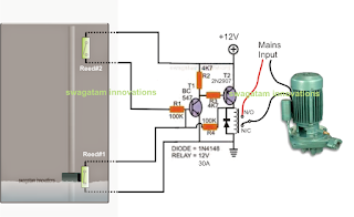
The post explains a simple single phase jet water pump controller circuit using magnetic reed switch level sensor, and a set/reset circuit. The idea was requested by Mr. Nanigopal mahata
The Request
sir, i am your blog follower,, i searched all the blogs for automatic submersible pump controller but i cant understand which one is single jet pump controller circuit....
The Request
sir, i am your blog follower,, i searched all the blogs for automatic submersible pump controller but i cant understand which one is single jet pump controller circuit....
help me out sir,, with a circuit diagram where i can use two 12 volt 10 amp relay(single pole single throw) , and two reed switch(for level sensing).
as the water tank full jet pump will automatic off and vise versa..
also mention the transformer rating to control the whole circuit, and mention the ic which one is suitable.. as soon as possible..
The Design
The diagram shows the proposed single phase water jet pump controller circuit consisting of water level sensors using reed switches, and a transistorized set reset latch stage.
I have already explained how to make reed switch based water sensors also called float switches, you can refer the linked article for a detailed info regarding the same.
The transistorized latch circuit is made through a couple of transistors which are designed to latch and delatch in response to the relevant reed switch operations.
The two reed switches as shown in the diagram are positioned to sense the high/low water levels, when the water level is low, the magnetic float is held near the lower reed switch, and when the water level reaches the top of the tank, the magnetic float approaches the upper reed switch. During both these occasions the relevant reed switch is actuated.
At the upper water level, the upper reed switch closes which in turn latches the transistor latch circuit, activating the relay.
The relay contacts then switch ON the connected single phase jet water pump motor.
The jet motor begins emptying the tank, until the water level reaches the lower threshold which actuates the lower reed switch, quickly breaking of the transistor latch.
With the latch disabled the relay is switched OFF. This action immediately stops the jet pump motor, until the tank is filled again upto the top to initiate the switching cycle.
Available link for download
Subscribe to:
Posts (Atom)