Showing posts with label phase. Show all posts
Showing posts with label phase. Show all posts
Wednesday, November 2, 2016
THREE PHASE INDUCTION MOTOR SAFETY IMPLEMENTATION
THREE PHASE INDUCTION MOTOR SAFETY IMPLEMENTATION
ABSTRACT:
The common problem with three-phase supply is, absence of any one of the phase. This leads to damage of induction motor or any three-phase load. This project is designed to monitor the presence of three phases and to display condition of each phase on an LCD. If any phase is absent, immediately this system shuts down the three-phase load. If all the three phases are present, automatically this system switches on the load.
This project is also designed to monitor the voltage condition of each phase. If the voltage level of any phase is over or under the rated / specified voltage rating, immediately this system shuts down the load. Operational amplifier IC LM324 is used here as a comparator. IC LM324 consists of four operational amplifiers, of which only two operational amplifiers are used in the project.
When the AC voltage increases beyond 240V, the voltage at the non-inverting terminal of operational amplifier increases. The voltage at the inverting terminal is still 6.8V because of the zener diode. Thus if the voltage at pin 3 of the operational amplifier is higher than 6.8V, the output of the operational amplifier goes high to drive transistor T1 and hence energise relay RL. Consequently, the AC supply is disconnected and electrical appliances turn off. Thus the appliances are protected against over-voltage. Now let’s consider the under-voltage condition. When the line voltage is below 180V, the voltage at the inverting terminal of operational amplifier is less than the voltage at the non-inverting terminal (6V). Thus the output of operational amplifier goes high and it energizes the relay through transistor. The AC supply is disconnected and electrical appliances turn off. Thus the appliances are protected against under-voltage.
BLOCK DIAGRAM:
Phase fault detector


If you want to buy this project, drop email on technofieldsystems@gmail.com
Available link for download

Wednesday, September 28, 2016
Single Phase Jet Pump Controller Circuit
Single Phase Jet Pump Controller Circuit
The post explains a simple single phase jet water pump controller circuit using magnetic reed switch level sensor, and a set/reset circuit. The idea was requested by Mr. Nanigopal mahata
The Request
sir, i am your blog follower,, i searched all the blogs for automatic submersible pump controller but i cant understand which one is single jet pump controller circuit....
The Request
sir, i am your blog follower,, i searched all the blogs for automatic submersible pump controller but i cant understand which one is single jet pump controller circuit....
help me out sir,, with a circuit diagram where i can use two 12 volt 10 amp relay(single pole single throw) , and two reed switch(for level sensing).
as the water tank full jet pump will automatic off and vise versa..
also mention the transformer rating to control the whole circuit, and mention the ic which one is suitable.. as soon as possible..
The Design
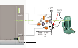
The diagram shows the proposed single phase water jet pump controller circuit consisting of water level sensors using reed switches, and a transistorized set reset latch stage.
I have already explained how to make reed switch based water sensors also called float switches, you can refer the linked article for a detailed info regarding the same.
The transistorized latch circuit is made through a couple of transistors which are designed to latch and delatch in response to the relevant reed switch operations.
The two reed switches as shown in the diagram are positioned to sense the high/low water levels, when the water level is low, the magnetic float is held near the lower reed switch, and when the water level reaches the top of the tank, the magnetic float approaches the upper reed switch. During both these occasions the relevant reed switch is actuated.
At the upper water level, the upper reed switch closes which in turn latches the transistor latch circuit, activating the relay.
The relay contacts then switch ON the connected single phase jet water pump motor.
The jet motor begins emptying the tank, until the water level reaches the lower threshold which actuates the lower reed switch, quickly breaking of the transistor latch.
With the latch disabled the relay is switched OFF. This action immediately stops the jet pump motor, until the tank is filled again upto the top to initiate the switching cycle.
Available link for download
Subscribe to:
Posts (Atom)