Showing posts with label control. Show all posts
Showing posts with label control. Show all posts
Wednesday, November 9, 2016
PC BASED DC MOTOR SPEED AND DIRECTION CONTROL USING PWM AND BRIDGE
PC BASED DC MOTOR SPEED AND DIRECTION CONTROL USING PWM AND BRIDGE
ABSTRACT:
A pulse width modulator (PWM) is a device that may be used as an efficient DC motor speed controller or light dimmer. This project is a versatile device that can control DC devices which draw up to a few amps of current. The circuit may be used in either 12 or 24 Volt systems with only a few minor wiring changes. This device has been used to control the speed of the DC motor and to control brightness of an automotive tail lamp.
A PWM circuit works by making a square wave with a variable on-to-off ratio, the average on time may be varied from 0 to 100 percent. In this manner, a variable amount of power is transferred to the load.
The main advantage of a PWM circuit over a resistive power controller is the efficiency, at a 50% level, the PWM will use about 50% of full power, almost all of which is transferred to the load, a resistive controller at 50% load power would consume about 71% of full power, 50% of the power goes to the load and the other 21% is wasted heating the series resistor.
One additional advantage of pulse width modulation is that the pulses reach the full supply voltage and will produce more torque in a motor by being able to overcome the internal motor resistances more easily. Two push-to-on switches are provided for increasing / decreasing the speed of the motor.
Two more push-to-on switches are provided to rotate the motor in Clock wise / Counter clock wise direction. 16X2 LCD is connected to display the speed level of the motor and the direction. LED indication is also provided for visual indication.
A buzzer is provided for audio indication of DC motor speed variation and change in direction. Whenever the speed is increased / decreased, the system acknowledges by a short beep. This buzzer is driven by transistor driver circuit.
This project uses regulated 5V, 750mA & 12V, 500mA power supply. 7805 and 7812 three terminal voltage regulators are used for voltage regulation. Bridge type full wave rectifier is used to rectify the ac out put of secondary of 230/12V step down transformer.

If you want to buy this project, drop email on technofieldsystems@gmail.com
Available link for download

Sunday, November 6, 2016
SMS BASED PWM SPEED AND DIRECTION CONTROL OF DC MOTOR USING H BRIDGE AND GSM
SMS BASED PWM SPEED AND DIRECTION CONTROL OF DC MOTOR USING H BRIDGE AND GSM
ABSTRACT:
Nowadays there are various electronic equipments available for remote operation of electronic devices. But, the main disadvantage of these systems is that they can be operated only in short ranges and also less reliable. Thus, to overcome the above drawbacks, we are using one of the wireless communication technique i.e., GSM.
GSM(Global Systems for Mobile Communication) is vastly used because of its simplicity in both transmitter and receiver design, can operate at 900 or 1800MHZ band, faster, more reliable and globally network. Here the system is capable of controlling the motor by receiving control messages from an authorized mobile number. Microcontroller is the heart of our system, which controls the overall operation of our system. System always alert for receiving SMS from valid number then that particular messages are displayed on our LCD(Liquid Crystal Display) i.e., whether the motor should rotate in right shift or left shift with a speed of so and so.
We are using H-Bridge as an driver for our DC Motor because our Microcontroller cannot provide the maximum current to drive a DC Motor. GSM network operators have roaming facilities, user can often continue to use there mobile phones when they travel to other countries etc. In contrast, a microcontroller not only accepts the data as inputs but also manipulates it, interfaces the data with various devices, controls the data and thus finally gives the result.
This project uses regulated 5V, 500mA power supply. 7805 three terminal voltage regulator is used for voltage regulation. Bridge type full wave rectifier is used to rectify the ac out put of secondary of 230/12V step down transformer.
BLOCK DIAGRAM:

If you want to buy this project, drop email on technofieldsystems@gmail.com
Available link for download
Wednesday, November 2, 2016
Remote Control Circuit Using Arduino
Remote Control Circuit Using Arduino
In this post, we are going to construct a remote control circuit for controlling home appliances using arduino microcontroller.
By: Girish Radhakrishnan
This circuit can turn on/off your gadgets using TV remote’s unused buttons or any other unused remote that may be lying in your junk box for ages.
The motto of this project is to help physically challenged persons, and help them to access the ON/OFF switching of the basic home appliances such as fans or lights independently.
The second objective is to enable the user to control the gadgets “Like a boss” without having to move from his or her existing position.
The circuit utilizes traditional IR based communication between transmitter and receiver.
This circuit is cent percent fool proof to other IR remotes, and other IR sources and less susceptible to errors.
The major problem with non-microcontroller based IR remote control circuit, which is found around the internet, is that it could turn ON/OFF with any IR based remote and can only control one device at an instant and also more susceptible to errors.
This circuit overcomes above specified issues, and we can control several gadgets on one remote and assign keys for specific gadgets.
Before proceeding this project you need to download the library files for arduino form this link and follow the instruction given below: https://github.com/z3t0/Arduino-IRremote
Instructions:
1) Click “clone or download” button form the given link and hit “Download ZIP”.
2) Extract the file and move “IRremote” folder to your library folder of Arduino.
3) Delete “RobotIRremote” folder from your arduino library. “RobotIRremote” has similar definition of “IRremote” library which clash and not able to upload the code to Arduino so, deletion/removal is mandatory.
By duplicating the above instruction your Arduino IDE software is ready for any/most of the IR based projects.
Assign keys for remote:
In our TV remote each key has unique hexadecimal code, which is used to recognize which key is pressed for an operation. Before uploading the final code to Arduino, you need to find what the hexadecimal codes for your keys are.
To do this construct the following circuit in breadboard and follow the instruction.
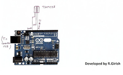
1) Open Arduino IDE and upload example code “IRrecv Demo”
2) Open serial monitor and press the key on remote that you want to use.
You’ll see hexadecimal code pop up as soon as you press the key. That’s the hexadecimal code for that particular key.
3) Do the same for other two keys (3 keys are given in this project for controlling 3 devices)
· We are going to use these hexadecimal codes in the main program and upload to arduino.
//-----------------Program developed by R.Girish-----------//
#include<IRremote.h>
int input = 11;
int op1 = 8;
int op2 = 9;
int op3 = 10;
int intitial1;
int intitial2;
int intitial3;
IRrecv irrecv(input);
decode_results dec;
#define output1 0x111 // place your code received from button A
#define output2 0x112 // place your code received from button B
#define output3 0x113 // place your code received from button C
void setup()
{
irrecv.enableIRIn();
pinMode(op1,1);
pinMode(op2,1);
pinMode(op3,1);
}
void loop() {
if (irrecv.decode(&dec)) {
unsigned int value = dec.value;
switch(value) {
case output1:
if(intitial1 == 1) {
digitalWrite(op1, LOW);
intitial1 = 0;
} else {
digitalWrite(op1, HIGH);
intitial1 = 1;
}
break;
case output2:
if(intitial2 == 1) {
digitalWrite(op2, LOW);
intitial2 = 0;
} else {
digitalWrite(op2, HIGH);
intitial2 = 1;
}
break;
case output3:
if(intitial3 == 1) {
digitalWrite(op3, LOW);
intitial3 = 0;
} else {
digitalWrite(op3, HIGH);
intitial3 = 1;
}
break;
}
irrecv.resume();
}
}
//--------------Program developed by R.Girish-----------//
NOTE:
In the program:
#define output1 0x111 // place your code received from button A
#define output2 0x111 // place your code received from button B
#define output3 0x111 // place your code received from button C
· Place your 3 unique codes from your remote in this place of 111, 112, and 113 and upload the code. Hexadecimal codes will be from 0 to 9 and A to F, for example: 20156, 26FE789, FFFFFF.
· Place your code with “0x” (zero x).
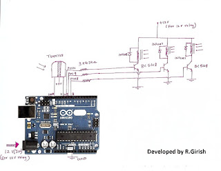
Circuit diagram:
· Pressing key trips the relay ON and by pressing again it will turn off the relay.
Available link for download
Thursday, October 6, 2016
RC Helicopter Remote Control Circuit
RC Helicopter Remote Control Circuit
Sir I am making a large scale rc helicopter. In which I am using 4 motors. For 1st main 12v motor: the mechanism is that I want its speed to be controlled by a controller key on the remote,from 0 to full speed.
For 2nd 3v motors: its mechanism is only for forward and reverse rotation with individual key on the remote for each motors as it will operate the swash plates of rotors.
For 3rd 9v tail motor: it should be set to an equilibrium speed using a regulator on the receiver board of helicopter so that I could adjust the speed manually to stop the chopper.. from rotating along with the rotors, and theres a key on the remote would be to slow down and speed up the motor from its equilibrium.
Sir the input power in the receiver board would be 12v and current 8-10 ampere. It should be of range 500-800 meters. Sir can you please design such a RC circuit board along with the remote.
I am in search of such circuit board since last two years.
My project was stopped due to its absence. Sir please help me. For your convenience you can design two individual rc circuit boards one for main motor and tail motor and another for two forward and reverse rotating motors.
But the input current and potential difference in both circuits should be same, with same range that is 500-800 meters with its remotes or remote. Please also mention the name of the components required with numbering...thanks
The Design
The requested circuit modules which are required for building the proposed RC helicopter are:
1) A 12V PWM variable speed controller
2) A 3V motor reverse forward controller circuit.
3) a 9V motor regulator with a variable speed controller circuit.
All the above specifications needs to be controlled via a long range 433MHz RF remote control module.
The desired 433MHz RF remote module could be procured from any online store or from your nearest electronic dealer. The range of the remote control should be as per the required specifications of the RC helicopter range, here its supposed to be within 1km.
For the discussed RC helicopter remote control circuit, a 6 channel RF remote module would be required, exactly similar to the one which was used for our earlier simplest drone remote control circuit.
The image of the same can be witnessed below:
 The left side green board is the remote receiver module having the six control relays and this units needs to be installed inside the RC helicopter for the necessary control operations.
The right side unit is the transmitter handset which is supposed to be held by the user and the relevant buttons pressed for commanding the relay board with the corresponding motion control info.
Now lets see how the six relays needs to be configured with the various PWM circuits and installed inside the RC chopper, from the following details:
Remember the relay contacts shown in the receiver board are all blank by default, meaning their N/C and N/O contacts are not wired and must be wired as illustrated in the following diagrams.
According to the request, the 9V motor and the 12V motor speeds need to be controlled through the subsequent pressing of the remote handset. The circuits for implementing this function are shown below:


As may be seen in the schematics, a couple of identical IC 555 PWM circuits are employed for the purpose. Four out of the six relays are engaged here with their relevant contacts wired across the shown connections.
In the design the IC 555 is rigged as a basic astable circuit, assigned to oscillate with some specified frequency depending upon its R1, R2, and C component values.
A voltage follower in the form of IC 741 is configured with the control pin#5 of the IC 555 in order to vary the PWM content at pin#3 of the IC 555 in accordance with the indicated relay operations.
The voltage at pin#3 of the IC 741 is followed or transferred at is pin#6 and subsequently to pin#5 of the IC 555. Depending upon pin#3 capacitor charge level this varying voltage could be anywhere between the supply voltage limit and zero.
The charge level on the capacitor is varied or changed by simply charging it or discharging via the relevant relay contact activation. To charge the upper relay contact is closed or activated enabling an rising voltage at pin#5 of IC 555 whereas activating the lower relay contacts discharges the capacitor causing a proportionately lower voltage to appear at pin#5 of the IC 555.
The above actions translate the pin#3 results into a correspondingly varying PWMs which in turn causes the motor to either run faster or slower.
Fro the 9V motor a series of diodes can be seen attached at the emitter of the driver transistor, this ensures the required drop in voltage and helps to convert the 12V into an approximate 10V regulated supply as per the specifications of the motor.
3V Motor Reverse Forward Operation
The third and the last demand in the request is for the reverse/forward control of the 3V motor using the RF transmitter handset button press.
The remaining two relays can eb now used for this particular execution, and is done as demonstrated in the following diagram:
 Here also we employ the versatile IC 555 wired as a precise PWM generator circuit. The PWM is set appropriately through the 5K preset before finalizing the installations such that the speed of the motor is perfectly adjusted for the required equilibrium of the helicopter.
The relays can be seen simply wired to enforce the required reverse, and forward or a clockwise or anticlockwise motion for the motor in response to the toggling of the paired relay contact, which together form a DPDT relay.
In order to prevent a short circuit, preferably the receiver module should be modified for these two relays such that pressing either of the buttons causes both the relays to activate together rather tan depending on two switches to be pressed in sync for the activation.
This toggling can be expected to flip the motor rotation in the opposite direction instantly allowing the user to execute the required directional changes in the RC helicopter machine.
This concludes the circuit and relay wiring instructions for the proposed RC helicopter remote control circuit, for further doubts please do not hesitate to express them through your comments.
For 2nd 3v motors: its mechanism is only for forward and reverse rotation with individual key on the remote for each motors as it will operate the swash plates of rotors.
For 3rd 9v tail motor: it should be set to an equilibrium speed using a regulator on the receiver board of helicopter so that I could adjust the speed manually to stop the chopper.. from rotating along with the rotors, and theres a key on the remote would be to slow down and speed up the motor from its equilibrium.
Sir the input power in the receiver board would be 12v and current 8-10 ampere. It should be of range 500-800 meters. Sir can you please design such a RC circuit board along with the remote.
I am in search of such circuit board since last two years.
My project was stopped due to its absence. Sir please help me. For your convenience you can design two individual rc circuit boards one for main motor and tail motor and another for two forward and reverse rotating motors.
But the input current and potential difference in both circuits should be same, with same range that is 500-800 meters with its remotes or remote. Please also mention the name of the components required with numbering...thanks
The Design
The requested circuit modules which are required for building the proposed RC helicopter are:
1) A 12V PWM variable speed controller
2) A 3V motor reverse forward controller circuit.
3) a 9V motor regulator with a variable speed controller circuit.
All the above specifications needs to be controlled via a long range 433MHz RF remote control module.
The desired 433MHz RF remote module could be procured from any online store or from your nearest electronic dealer. The range of the remote control should be as per the required specifications of the RC helicopter range, here its supposed to be within 1km.
For the discussed RC helicopter remote control circuit, a 6 channel RF remote module would be required, exactly similar to the one which was used for our earlier simplest drone remote control circuit.
The image of the same can be witnessed below:
The right side unit is the transmitter handset which is supposed to be held by the user and the relevant buttons pressed for commanding the relay board with the corresponding motion control info.
Now lets see how the six relays needs to be configured with the various PWM circuits and installed inside the RC chopper, from the following details:
Remember the relay contacts shown in the receiver board are all blank by default, meaning their N/C and N/O contacts are not wired and must be wired as illustrated in the following diagrams.
According to the request, the 9V motor and the 12V motor speeds need to be controlled through the subsequent pressing of the remote handset. The circuits for implementing this function are shown below:
As may be seen in the schematics, a couple of identical IC 555 PWM circuits are employed for the purpose. Four out of the six relays are engaged here with their relevant contacts wired across the shown connections.
In the design the IC 555 is rigged as a basic astable circuit, assigned to oscillate with some specified frequency depending upon its R1, R2, and C component values.
A voltage follower in the form of IC 741 is configured with the control pin#5 of the IC 555 in order to vary the PWM content at pin#3 of the IC 555 in accordance with the indicated relay operations.
The voltage at pin#3 of the IC 741 is followed or transferred at is pin#6 and subsequently to pin#5 of the IC 555. Depending upon pin#3 capacitor charge level this varying voltage could be anywhere between the supply voltage limit and zero.
The charge level on the capacitor is varied or changed by simply charging it or discharging via the relevant relay contact activation. To charge the upper relay contact is closed or activated enabling an rising voltage at pin#5 of IC 555 whereas activating the lower relay contacts discharges the capacitor causing a proportionately lower voltage to appear at pin#5 of the IC 555.
The above actions translate the pin#3 results into a correspondingly varying PWMs which in turn causes the motor to either run faster or slower.
Fro the 9V motor a series of diodes can be seen attached at the emitter of the driver transistor, this ensures the required drop in voltage and helps to convert the 12V into an approximate 10V regulated supply as per the specifications of the motor.
3V Motor Reverse Forward Operation
The third and the last demand in the request is for the reverse/forward control of the 3V motor using the RF transmitter handset button press.
The remaining two relays can eb now used for this particular execution, and is done as demonstrated in the following diagram:
The relays can be seen simply wired to enforce the required reverse, and forward or a clockwise or anticlockwise motion for the motor in response to the toggling of the paired relay contact, which together form a DPDT relay.
In order to prevent a short circuit, preferably the receiver module should be modified for these two relays such that pressing either of the buttons causes both the relays to activate together rather tan depending on two switches to be pressed in sync for the activation.
This toggling can be expected to flip the motor rotation in the opposite direction instantly allowing the user to execute the required directional changes in the RC helicopter machine.
This concludes the circuit and relay wiring instructions for the proposed RC helicopter remote control circuit, for further doubts please do not hesitate to express them through your comments.
Available link for download
Sunday, August 28, 2016
Take Control of Your Smartphone’s Automatic Photo Uploads
Take Control of Your Smartphone’s Automatic Photo Uploads

Current cell phones and cloud photograph administrations need to naturally transfer each and every photograph you take to the cloud. Be that as it may, you would prefer dependably not to spare each photograph always on those remote servers.
Programmed photograph transferring guarantees each one of those photographs you take are securely went down some place, however it isnt perfect for each and every photograph. Lamentably, organizations like Apple and Google havent gotten that message.
Pick Whether You Want to Automatically Upload Photos or Not
Contingent upon the applications youve introduced and designed, you might have a few applications transferring your photographs to distinctive areas — for instance, the implicit iCloud Photos highlight on an iPhone and the Dropbox application, or the inherent Google+ application on an Android telephone and the Microsoft OneDrive application.
iPhones and iPads have programmed photograph transfer through iCloud Photo Library. On the off chance that youve empowered iCloud, theres a decent risk you empowered the photograph library highlight which transfers the photographs you take to your iCloud stockpiling. Before long there will be no senseless impediments on the quantity of photographs you can store — you can store every one of the photographs you like, the length of you have some free space in iCloud.
Open the Settings application, tap the iCloud classification, and tap Photos. Utilize the alternatives here to control whether your iPhone or iPad transfers the photographs you take to iCloud.
Android gadgets have programmed photograph transfer through in the "Auto Backup" highlight in the Photos application, which stores your photographs in Google+ Photos (in the past known as Picasa Web Albums.) If youve opened the Google+ application and consented to the brief, theres a decent risk you have this empowered.
Dispatch the Photos application on your Android telephone or tablet, tap the menu catch, tap Settings, and tap Auto Backup. Utilize the choices here to control whether your Android gadget transfers your photographs to your Google+ account.
Whether youre utilizing an iPhone or Android telephone, distributed storage applications like Google+, Dropbox, Microsoft OneDrive, and Flickr can consequently transfer your photographs to the cloud in the event that youve introduced the application and empowered this component. On Windows Phone, the implicit photograph transfer highlight transfers your photographs to OneDrive.
On both gadgets, check any cloud-record capacity or photograph transferring applications youve introduced and ensure photograph transfers are debilitated on the off chance that you would prefer not to utilize them. For instance, on Dropbox for iOS, youll discover this choice under Settings > Camera Upload.
View Photos Youve Uploaded, and Delete Ones You Dont Want to Keep
In the event that you take a delicate photograph — or only a photograph you would prefer not to keep perpetually, in light of the fact that youd rather keep the great ones and not include mess and squander space with the terrible ones — you cant simply erase it on your cell phone to dispose of it. You need to go into the photograph transferring administration itself and erase the photograph from their servers, as well.
For Apples iCloud, you can right now get to these photographs in the Photos application on an iOS gadget, in iPhoto on a Mac, or by means of the Photos sync highlight in the iCloud control board for Windows. Erase any photographs you would prefer not to find in the cloud.
For Google+, you can get to the Google+ Photos site, tap the All Photos choice to see every one of your photographs, select the photographs you would prefer not to keep, and erase them.
For Dropbox and OneDrive, youll simply discover your photographs transferred as documents in your distributed storage account. For instance, in Dropbox youll see them under the Photos view or under the Camera Upload envelope in your rundown of records. You can get to these on your desktop with the Dropbox sync customer, on the Dropbox site, or in a Dropbox versatile application.
For different administrations like Flickr, it works like youd expect — theyll be accessible as photographs in your Flickr account, for instance.
Take Photos and Keep Them Private
Be that as it may, imagine a scenario in which you need to take a photograph without having it transferred to the cloud by any means. Hell, perhaps youre taking photographs of imperative lawful or budgetary archives rather to sweep them. You most likely dont need duplicates of those delicate records put away in Google+, iCloud, or Dropbox until the end of time.
Staying away from the programmed photograph transfer is really somewhat intense. Theres no real way to put the inherent Camera application on iOS or Android into a "kindly dont-transfer these-photographs" mode. Each photograph you take it transferred. In the event that you need to evacuate them, youll need to erase them from the online stockpiling benefit later. In the event that you dont need them to transfer, youll need to pre-emptively cripple the photograph transferring highlights before taking that photograph. In any case, on the off chance that you empower the photograph transferring highlight a short time later, itll likely transfer those photographs in the event that you havent erased them yet.
Filling the crevice are outsider "private camera"- sort applications that permit you to take photographs without putting away them in the framework wide Camera Roll on iOS or Photos on Android. The key here is that the "private camera" application takes photographs and keeps them inside of the application itself, keeping the framework wide photograph stockpiling from getting to and after that naturally transferring them. This isnt a perfect arrangement, yet keeping the photographs separate from the framework wide photographs highlight is the best way to guarantee theyre not transferred.
You could likewise debilitate photograph transfers for all time or simply permit them to transfer and erase them from the distributed storage later. Yet, in the event that theyre delicate, make sure youve cleared your rubbish a while later!
private camera
Obviously, you dont need to utilize programmed photograph transfers. You could simply just physically transfer the photographs you jump at the chance to your distributed storage administration of decision, or even join your telephone to your PC to exchange your photographs off and oversee them the way it was done in the good ol days. Be that as it may, it would be decent in the event that we had more control over which photographs are transferred and which kept focused telephones at the framework
Available link for download
Thursday, August 25, 2016
Remote Control Camera Switching Circuit
Remote Control Camera Switching Circuit
The article discusses a simple RF remote control circuit which can be used for activating a digital camera remotely, by a press of a button. The idea was requested by Mr. Pat
The Request
Hi Swagatam,
Im Pat, from France. Congratulations for your blog & website about electronics devices : its the paradise :o)
Im photographer & im looking for a simple remote control for my Nikon D200 in RF. I need a transmitter and receiver in a single radio frequencies with good reach and operate on a 9V battery. the goal is to trigger the camera remotely. The Nikon camera has a 10-pin socket designed for it.
Heres a business model but very expensive here :

Would you have an assembly to propose? (I tinker with classical electronics as ham radio... :o)
thanks for your help :o)
Patrick / F5CEY
~90 miles north of Paris
France
May I ask you what area youre in the USA ?


My Reply
Hi Pat,
I am glad you liked my website. Ill to try post the design as per my analysis soon in my website. In the meantime you can go through the following article which I would be using for the proposed implementation. http://www.homemade-circuits.com/2013/07/simple-100-meter-rf-module-remote.html
I am situated in India, my website host operates from the USA:)
Best Regards
Swag.
The Design
I have discussed a simple 433 MHz RF remote control module based circuits which can be used in all kinds of remote switching applications within a range of 100 meters. Other forms of modules can be employed for getting higher ranges of distance.
These RF remote control modules can be also effectively used for the discussed remote camera switching application.
As per my interpretation, the pinouts from the cameras 10 pin socket which are relevant to the remote switching of the camera (using the proposed RF modules) are as follows:
pin#1 = Rx input data (triggering pulse)
pin#2 = +5V external input, or from the camera battery
pin#7 = power ground to be integrated with the RF module ground or negative.
Other pinouts does not look relevant for the intended functions and therefore may be left open.
As per the above data, the Rx or receiver module output could be integrated with the cameras existing 10 pin connector in the following shown manner:

If the camera is intended to be operated with an external power source then an external battery may be utilized for powering the Rx module and the same may be fed to the camera via the pin#2 of its 10 pin socket.
If the internal battery of the camera is used which looks more appropriate then the Rx module could be powered from this source via the pin#2.
The BC557 can be seen configured with one of the output pinouts of the RX module which happens to be pin#10 from the decoder IC of the Rx module, although any of the other output could be used for the same results.
In the Tx module you will also find compatible 4 inputs with switches, each corresponding to the individual 4 outputs of the Rx module, meaning if pin#10 button of the Tx is pressed, this will activate the pin#10 of the Rx module.... and so on.
Therefore in the above case the pin#10 switch of the Tx needs to be pressed for implementing the required remote controlled camera switching.
The press of a button in the Tx handset is supposed to generate a low logic at the relevant pinout of the Rx module (pin#10 in the present case), which causes the BBC557 to activate and send a +5V TTL pulse to pin#1 of the camera, activating the camera shutters.
The following circuit depicts the transmitter circuit or the Tx circuit stage which is supposed to be utilized for triggering the camera located in the remote location:
 As can be seen in the above image, the four switches correspond to the respective 4 outputs of the Rx module.
However since pin#10 is employed in the present design, the switch associated with pin#10 should be used which is indicated as SW1 in the above diagram. The rest of the switches could be ignored.
The Request
Hi Swagatam,
Im Pat, from France. Congratulations for your blog & website about electronics devices : its the paradise :o)
Im photographer & im looking for a simple remote control for my Nikon D200 in RF. I need a transmitter and receiver in a single radio frequencies with good reach and operate on a 9V battery. the goal is to trigger the camera remotely. The Nikon camera has a 10-pin socket designed for it.
Heres a business model but very expensive here :
Would you have an assembly to propose? (I tinker with classical electronics as ham radio... :o)
thanks for your help :o)
Patrick / F5CEY
~90 miles north of Paris
France
May I ask you what area youre in the USA ?
My Reply
Hi Pat,
I am glad you liked my website. Ill to try post the design as per my analysis soon in my website. In the meantime you can go through the following article which I would be using for the proposed implementation. http://www.homemade-circuits.com/2013/07/simple-100-meter-rf-module-remote.html
I am situated in India, my website host operates from the USA:)
Best Regards
Swag.
The Design
I have discussed a simple 433 MHz RF remote control module based circuits which can be used in all kinds of remote switching applications within a range of 100 meters. Other forms of modules can be employed for getting higher ranges of distance.
These RF remote control modules can be also effectively used for the discussed remote camera switching application.
As per my interpretation, the pinouts from the cameras 10 pin socket which are relevant to the remote switching of the camera (using the proposed RF modules) are as follows:
pin#1 = Rx input data (triggering pulse)
pin#2 = +5V external input, or from the camera battery
pin#7 = power ground to be integrated with the RF module ground or negative.
Other pinouts does not look relevant for the intended functions and therefore may be left open.
As per the above data, the Rx or receiver module output could be integrated with the cameras existing 10 pin connector in the following shown manner:
If the camera is intended to be operated with an external power source then an external battery may be utilized for powering the Rx module and the same may be fed to the camera via the pin#2 of its 10 pin socket.
If the internal battery of the camera is used which looks more appropriate then the Rx module could be powered from this source via the pin#2.
The BC557 can be seen configured with one of the output pinouts of the RX module which happens to be pin#10 from the decoder IC of the Rx module, although any of the other output could be used for the same results.
In the Tx module you will also find compatible 4 inputs with switches, each corresponding to the individual 4 outputs of the Rx module, meaning if pin#10 button of the Tx is pressed, this will activate the pin#10 of the Rx module.... and so on.
Therefore in the above case the pin#10 switch of the Tx needs to be pressed for implementing the required remote controlled camera switching.
The press of a button in the Tx handset is supposed to generate a low logic at the relevant pinout of the Rx module (pin#10 in the present case), which causes the BBC557 to activate and send a +5V TTL pulse to pin#1 of the camera, activating the camera shutters.
The Transmitter circuit for the proposed remote control camera switching circuit
The following circuit depicts the transmitter circuit or the Tx circuit stage which is supposed to be utilized for triggering the camera located in the remote location:
However since pin#10 is employed in the present design, the switch associated with pin#10 should be used which is indicated as SW1 in the above diagram. The rest of the switches could be ignored.
Available link for download
Subscribe to:
Posts (Atom)
The Request
Jite Bently June 4, 2016 at 1:44 PM