Showing posts with label remote. Show all posts
Showing posts with label remote. Show all posts
Wednesday, November 2, 2016
Remote Control Circuit Using Arduino
Remote Control Circuit Using Arduino
In this post, we are going to construct a remote control circuit for controlling home appliances using arduino microcontroller.
By: Girish Radhakrishnan
This circuit can turn on/off your gadgets using TV remote’s unused buttons or any other unused remote that may be lying in your junk box for ages.
The motto of this project is to help physically challenged persons, and help them to access the ON/OFF switching of the basic home appliances such as fans or lights independently.
The second objective is to enable the user to control the gadgets “Like a boss” without having to move from his or her existing position.
The circuit utilizes traditional IR based communication between transmitter and receiver.
This circuit is cent percent fool proof to other IR remotes, and other IR sources and less susceptible to errors.
The major problem with non-microcontroller based IR remote control circuit, which is found around the internet, is that it could turn ON/OFF with any IR based remote and can only control one device at an instant and also more susceptible to errors.
This circuit overcomes above specified issues, and we can control several gadgets on one remote and assign keys for specific gadgets.
Before proceeding this project you need to download the library files for arduino form this link and follow the instruction given below: https://github.com/z3t0/Arduino-IRremote
Instructions:
1) Click “clone or download” button form the given link and hit “Download ZIP”.
2) Extract the file and move “IRremote” folder to your library folder of Arduino.
3) Delete “RobotIRremote” folder from your arduino library. “RobotIRremote” has similar definition of “IRremote” library which clash and not able to upload the code to Arduino so, deletion/removal is mandatory.
By duplicating the above instruction your Arduino IDE software is ready for any/most of the IR based projects.
Assign keys for remote:
In our TV remote each key has unique hexadecimal code, which is used to recognize which key is pressed for an operation. Before uploading the final code to Arduino, you need to find what the hexadecimal codes for your keys are.
To do this construct the following circuit in breadboard and follow the instruction.
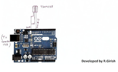
1) Open Arduino IDE and upload example code “IRrecv Demo”
2) Open serial monitor and press the key on remote that you want to use.
You’ll see hexadecimal code pop up as soon as you press the key. That’s the hexadecimal code for that particular key.
3) Do the same for other two keys (3 keys are given in this project for controlling 3 devices)
· We are going to use these hexadecimal codes in the main program and upload to arduino.
//-----------------Program developed by R.Girish-----------//
#include<IRremote.h>
int input = 11;
int op1 = 8;
int op2 = 9;
int op3 = 10;
int intitial1;
int intitial2;
int intitial3;
IRrecv irrecv(input);
decode_results dec;
#define output1 0x111 // place your code received from button A
#define output2 0x112 // place your code received from button B
#define output3 0x113 // place your code received from button C
void setup()
{
irrecv.enableIRIn();
pinMode(op1,1);
pinMode(op2,1);
pinMode(op3,1);
}
void loop() {
if (irrecv.decode(&dec)) {
unsigned int value = dec.value;
switch(value) {
case output1:
if(intitial1 == 1) {
digitalWrite(op1, LOW);
intitial1 = 0;
} else {
digitalWrite(op1, HIGH);
intitial1 = 1;
}
break;
case output2:
if(intitial2 == 1) {
digitalWrite(op2, LOW);
intitial2 = 0;
} else {
digitalWrite(op2, HIGH);
intitial2 = 1;
}
break;
case output3:
if(intitial3 == 1) {
digitalWrite(op3, LOW);
intitial3 = 0;
} else {
digitalWrite(op3, HIGH);
intitial3 = 1;
}
break;
}
irrecv.resume();
}
}
//--------------Program developed by R.Girish-----------//
NOTE:
In the program:
#define output1 0x111 // place your code received from button A
#define output2 0x111 // place your code received from button B
#define output3 0x111 // place your code received from button C
· Place your 3 unique codes from your remote in this place of 111, 112, and 113 and upload the code. Hexadecimal codes will be from 0 to 9 and A to F, for example: 20156, 26FE789, FFFFFF.
· Place your code with “0x” (zero x).
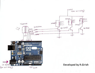
Circuit diagram:
· Pressing key trips the relay ON and by pressing again it will turn off the relay.
Available link for download

Friday, October 28, 2016
RF Controlled Metal Detecting Robot with Remote Voice and Image Transmission to assist Bomb Detection and Rescue Team
RF Controlled Metal Detecting Robot with Remote Voice and Image Transmission to assist Bomb Detection and Rescue Team
ABSTRACT:
Path Finder was sent to Mars in 1998. This was a great achievement which detected the secrets of “Mars”. This project deals with RF controlled robot. This robot is prototype for the “Path Finder”.
This robot is controlled by a RF remote. This can be moved forward and reverse direction using geared motors of 60RPM. Also this robot can take sharp turnings towards left and right directions. This project uses AT89S52 MCU as its controller. A high sensitive induction type metal detector is designed using colpitts oscillator principle and fixed to this robot. Also a wireless camera with voice is interfaced to the kit.
When the robot is moving on a surface, the system produces a beep sound when metal is detected. This beep sound will be transmitted to remote place. Simultaneously the images around the robot will be transmitted to remote place. User can monitor the images and metal detection alarms on Television.
The RF modules used here are STT-433 MHz Transmitter, STR-433 MHz Receiver, HT12E RF Encoder and HT12D RF Decoder. The three switches are interfaced to the RF transmitter through RF Encoder. The encoder continuously reads the status of the switches, passes the data to the RF transmitter and the transmitter transmits the data.
This project uses 9V battery. This project is much useful for mines detection and surveillance applications.


If you want to buy this project, drop email on technofieldsystems@gmail.com
Available link for download
Wednesday, October 12, 2016
Remote Controlled Submersible Pump Circuit
Remote Controlled Submersible Pump Circuit
The article discusses a simple remote controlled submersible pump circuit which could be simply configured using any standard 2 channel 433MHz remote control modules. The idea was requested by Mr. James Smith
The Request
Hi swagatam , I have read a lot of your post and have implemented them several time.
Now I want a design for switching my submersible single phase motor on and off via remote control.
On the starter there a push button for on and push button for off.
The push button is pushed only for 2 seconds and released and the motor is ON.
The same for stop. The push button is pushed for 2 seconds and the motor is OFF.
Pls help me in doing this as we are having trouble going up and down the staircase from 7 floor to ground floor to just ON and OFF the submersible motor.
If the circuit is ready, I will just connect it to the push buttons.?
James Smith
The Design
We have already witnessed the basic triggering concept of a submersible pump using an automatic "start" and "stop" implementation of the pump contactor switches.
In this remote controlled submersible pump circuit also we follow a similar concept but instead of water sensors, here we do it using a remote controlled modules and subsequent momentary relays switching for initiating the relevant start stop buttons.
For this we can employ a two channel 433 MHz RF remote control modules, which are extremely accurate with their working.
 I would recommend buying this unit instead of building one, because these are quite cheap and are easily accessible through online electronic stores.
However if you are interested to make it, you could try it out by procuring the recommended chips for these remote controlled modules which are also available through all standard online electronic retailer.
If you purchase the units readymade, then its just about configuring the relay contacts with the submersible start, and stop buttons, as shown below.
To be precise, its the N/O and the pole of the relays which needs to be connected across the submersible buttons.
For identifying the relay contacts of the remote receiver unit one may take the help of one my earlier pasts which explained how to understand and use relays in circuits.
However since the contactor start stop buttons could be specified to work with high switching current, these may require special high current relay driver stages for the individual buttons.
Therefore the triggering supply from the remote receiver relays needs to be further integrated with the above mentioned high power relay driver stages as demonstrated in the following figure:

The relay driver stages shown at the right side of the diagram is made by configuring transistor relay drivers with the respective high power relays.
The bases of the transistors can be seen connected with series high value capacitors, this is to ensure that the relays remain activated only for a couple of seconds, regardless of the switching periods of the remote control modules relays, or regardless of how long the user keeps the remote transmitter handset button pressed.
The shown remote control receiver module consisting of the receiver circuitry and the two relays will need 12V supply from an appropriate DC source, such as a 12V AC DC adapter.
This 12V further needs to be configured with the relay contacts and the relay driver stages also, for enabling the intended remote controlled start/stop switching of the submersible ON/OFF buttons.
The Request
Hi swagatam , I have read a lot of your post and have implemented them several time.
Now I want a design for switching my submersible single phase motor on and off via remote control.
On the starter there a push button for on and push button for off.
The push button is pushed only for 2 seconds and released and the motor is ON.
The same for stop. The push button is pushed for 2 seconds and the motor is OFF.
Pls help me in doing this as we are having trouble going up and down the staircase from 7 floor to ground floor to just ON and OFF the submersible motor.
If the circuit is ready, I will just connect it to the push buttons.?
James Smith
The Design
We have already witnessed the basic triggering concept of a submersible pump using an automatic "start" and "stop" implementation of the pump contactor switches.
In this remote controlled submersible pump circuit also we follow a similar concept but instead of water sensors, here we do it using a remote controlled modules and subsequent momentary relays switching for initiating the relevant start stop buttons.
For this we can employ a two channel 433 MHz RF remote control modules, which are extremely accurate with their working.
However if you are interested to make it, you could try it out by procuring the recommended chips for these remote controlled modules which are also available through all standard online electronic retailer.
If you purchase the units readymade, then its just about configuring the relay contacts with the submersible start, and stop buttons, as shown below.
To be precise, its the N/O and the pole of the relays which needs to be connected across the submersible buttons.
For identifying the relay contacts of the remote receiver unit one may take the help of one my earlier pasts which explained how to understand and use relays in circuits.
However since the contactor start stop buttons could be specified to work with high switching current, these may require special high current relay driver stages for the individual buttons.
Therefore the triggering supply from the remote receiver relays needs to be further integrated with the above mentioned high power relay driver stages as demonstrated in the following figure:
The relay driver stages shown at the right side of the diagram is made by configuring transistor relay drivers with the respective high power relays.
The bases of the transistors can be seen connected with series high value capacitors, this is to ensure that the relays remain activated only for a couple of seconds, regardless of the switching periods of the remote control modules relays, or regardless of how long the user keeps the remote transmitter handset button pressed.
The shown remote control receiver module consisting of the receiver circuitry and the two relays will need 12V supply from an appropriate DC source, such as a 12V AC DC adapter.
This 12V further needs to be configured with the relay contacts and the relay driver stages also, for enabling the intended remote controlled start/stop switching of the submersible ON/OFF buttons.
Available link for download
Friday, October 7, 2016
Remote Infrared Wireless Alarm Circuit
Remote Infrared Wireless Alarm Circuit
A simple infrared wireless alarm circuit can be built using an RF remote control unit a TSOP based IR sensor, lets learn the procedures in detail.
In a few of the other posts I have discussed regarding these RF remote control modules. For more info you may go through the following relevant article:
In this article we employ one of the above methods, and implement the proposed infrared wireless alarm circuit as explained below:
The idea is very simple, the infrared circuit is integrated with the Tx (transmitter) module, such that as long as the IR beam is not disturbed by an intruder the Tx switch is kept deactivated, and the moment the IR beam is interrupted by an intruder, the TX switch is triggered which in turn triggers the remote Rx relay and the associated alarm.

The above configuration depicts the IR wireless alarm transmitter circuit stage set up, wherein the TSW434 forms the standard RF transmitter chip, while the HT-12E is configured as an RF encoder IC.
A IR generator stage can be also seen which is used for generating and focusing an IR beam on the sensor of the IR encoder/transmitter stage.
This IR beam is positioned and stretched across the premise which needs to be guarded.
In the transmitter stage the encoder IC includes 4 inputs all of which require a ground or negative trigger to activate the encoder IC and prompt the TWS to send a corresponding encoded pulse signal in the air within the range of 50 meters.
Depending on the users requirement, only a single stage may be used or all the four stages may be engaged in order to monitor 4 different critical zones needing protection against a possible intrusion or a break in.
The IR sensor stage incorporates a standard TSOP17XX series sensor IC, which is configured with a PNP BC557 transistor amplifier stgae for amplifying the relatively smaller electrical pulses from the sensor to a 5V output.
As long as the IR beam stays focused and incident on the TSOP sensor, the BC557 is held switched ON which ensures a positive potential over the relevant input pin of the encoder IC.
In an event this IR beam is cut-off due a human passing by across the restricted zone, the BC557 is interrupted for that moment which in turn causes a ground signal to appear at the particular input of the encoder pin.
This action instantly initiates the TWS chip to send out a correspondingly encoded pulse in the air which is supposed to be received by the receiver unit or the decoder receiver unit positioned at some desired remote location within the specified radial range, near the user.

A complementary RF receiver decoder stage can be seen in the above diagram which is configured to receive the signal transmitted by the transmitter stage explained in the previous section.
Here the RSW is positioned to pick up the transmitted signal from the earlier explained TWS IC, and forward the encoded signal to the attached HT-12D decoder IC. This IC then appropriately decodes the received signals, converting them to a logic based signal across its one of the relevant output pins.
Pins 10 to 13 form the output pins of the decoder IC which produces the corresponding logic outputs for an external driver stage.
Here the driver stage is formed through a PNP NC557 and a relay suitably wired for the toggling the connected load which can be an alarm unit.
As may be seen, all the output pins from the decoder IC are made parallel or tied up together and integrated with the relay driver stage.
This makes sure that the relay driver is able to trigger in response to the activation of any of the transmitter input pins which may be configured with a separate TSOP sensor across different critical locations.
The infrared frequency generator as indicated in the first Tx circuit stage could be built by using a IC 555 wired in its standard astable mode with a frequency set at 38kHz.
The above discussed remote infrared wireless alarm circuit set up can be implemented for monitoring any desired critical location remotely within a radial distance of around 50 meters or more depending on which RF module is employed.
In a few of the other posts I have discussed regarding these RF remote control modules. For more info you may go through the following relevant article:
In this article we employ one of the above methods, and implement the proposed infrared wireless alarm circuit as explained below:
The idea is very simple, the infrared circuit is integrated with the Tx (transmitter) module, such that as long as the IR beam is not disturbed by an intruder the Tx switch is kept deactivated, and the moment the IR beam is interrupted by an intruder, the TX switch is triggered which in turn triggers the remote Rx relay and the associated alarm.
The Transmitter Circuit
The above configuration depicts the IR wireless alarm transmitter circuit stage set up, wherein the TSW434 forms the standard RF transmitter chip, while the HT-12E is configured as an RF encoder IC.
A IR generator stage can be also seen which is used for generating and focusing an IR beam on the sensor of the IR encoder/transmitter stage.
This IR beam is positioned and stretched across the premise which needs to be guarded.
In the transmitter stage the encoder IC includes 4 inputs all of which require a ground or negative trigger to activate the encoder IC and prompt the TWS to send a corresponding encoded pulse signal in the air within the range of 50 meters.
Depending on the users requirement, only a single stage may be used or all the four stages may be engaged in order to monitor 4 different critical zones needing protection against a possible intrusion or a break in.
The IR sensor stage incorporates a standard TSOP17XX series sensor IC, which is configured with a PNP BC557 transistor amplifier stgae for amplifying the relatively smaller electrical pulses from the sensor to a 5V output.
As long as the IR beam stays focused and incident on the TSOP sensor, the BC557 is held switched ON which ensures a positive potential over the relevant input pin of the encoder IC.
In an event this IR beam is cut-off due a human passing by across the restricted zone, the BC557 is interrupted for that moment which in turn causes a ground signal to appear at the particular input of the encoder pin.
This action instantly initiates the TWS chip to send out a correspondingly encoded pulse in the air which is supposed to be received by the receiver unit or the decoder receiver unit positioned at some desired remote location within the specified radial range, near the user.
The Receiver Stage
A complementary RF receiver decoder stage can be seen in the above diagram which is configured to receive the signal transmitted by the transmitter stage explained in the previous section.
Here the RSW is positioned to pick up the transmitted signal from the earlier explained TWS IC, and forward the encoded signal to the attached HT-12D decoder IC. This IC then appropriately decodes the received signals, converting them to a logic based signal across its one of the relevant output pins.
Pins 10 to 13 form the output pins of the decoder IC which produces the corresponding logic outputs for an external driver stage.
Here the driver stage is formed through a PNP NC557 and a relay suitably wired for the toggling the connected load which can be an alarm unit.
As may be seen, all the output pins from the decoder IC are made parallel or tied up together and integrated with the relay driver stage.
This makes sure that the relay driver is able to trigger in response to the activation of any of the transmitter input pins which may be configured with a separate TSOP sensor across different critical locations.
The infrared frequency generator as indicated in the first Tx circuit stage could be built by using a IC 555 wired in its standard astable mode with a frequency set at 38kHz.
The above discussed remote infrared wireless alarm circuit set up can be implemented for monitoring any desired critical location remotely within a radial distance of around 50 meters or more depending on which RF module is employed.
Available link for download
Thursday, October 6, 2016
RC Helicopter Remote Control Circuit
RC Helicopter Remote Control Circuit
Sir I am making a large scale rc helicopter. In which I am using 4 motors. For 1st main 12v motor: the mechanism is that I want its speed to be controlled by a controller key on the remote,from 0 to full speed.
For 2nd 3v motors: its mechanism is only for forward and reverse rotation with individual key on the remote for each motors as it will operate the swash plates of rotors.
For 3rd 9v tail motor: it should be set to an equilibrium speed using a regulator on the receiver board of helicopter so that I could adjust the speed manually to stop the chopper.. from rotating along with the rotors, and theres a key on the remote would be to slow down and speed up the motor from its equilibrium.
Sir the input power in the receiver board would be 12v and current 8-10 ampere. It should be of range 500-800 meters. Sir can you please design such a RC circuit board along with the remote.
I am in search of such circuit board since last two years.
My project was stopped due to its absence. Sir please help me. For your convenience you can design two individual rc circuit boards one for main motor and tail motor and another for two forward and reverse rotating motors.
But the input current and potential difference in both circuits should be same, with same range that is 500-800 meters with its remotes or remote. Please also mention the name of the components required with numbering...thanks
The Design
The requested circuit modules which are required for building the proposed RC helicopter are:
1) A 12V PWM variable speed controller
2) A 3V motor reverse forward controller circuit.
3) a 9V motor regulator with a variable speed controller circuit.
All the above specifications needs to be controlled via a long range 433MHz RF remote control module.
The desired 433MHz RF remote module could be procured from any online store or from your nearest electronic dealer. The range of the remote control should be as per the required specifications of the RC helicopter range, here its supposed to be within 1km.
For the discussed RC helicopter remote control circuit, a 6 channel RF remote module would be required, exactly similar to the one which was used for our earlier simplest drone remote control circuit.
The image of the same can be witnessed below:
 The left side green board is the remote receiver module having the six control relays and this units needs to be installed inside the RC helicopter for the necessary control operations.
The right side unit is the transmitter handset which is supposed to be held by the user and the relevant buttons pressed for commanding the relay board with the corresponding motion control info.
Now lets see how the six relays needs to be configured with the various PWM circuits and installed inside the RC chopper, from the following details:
Remember the relay contacts shown in the receiver board are all blank by default, meaning their N/C and N/O contacts are not wired and must be wired as illustrated in the following diagrams.
According to the request, the 9V motor and the 12V motor speeds need to be controlled through the subsequent pressing of the remote handset. The circuits for implementing this function are shown below:


As may be seen in the schematics, a couple of identical IC 555 PWM circuits are employed for the purpose. Four out of the six relays are engaged here with their relevant contacts wired across the shown connections.
In the design the IC 555 is rigged as a basic astable circuit, assigned to oscillate with some specified frequency depending upon its R1, R2, and C component values.
A voltage follower in the form of IC 741 is configured with the control pin#5 of the IC 555 in order to vary the PWM content at pin#3 of the IC 555 in accordance with the indicated relay operations.
The voltage at pin#3 of the IC 741 is followed or transferred at is pin#6 and subsequently to pin#5 of the IC 555. Depending upon pin#3 capacitor charge level this varying voltage could be anywhere between the supply voltage limit and zero.
The charge level on the capacitor is varied or changed by simply charging it or discharging via the relevant relay contact activation. To charge the upper relay contact is closed or activated enabling an rising voltage at pin#5 of IC 555 whereas activating the lower relay contacts discharges the capacitor causing a proportionately lower voltage to appear at pin#5 of the IC 555.
The above actions translate the pin#3 results into a correspondingly varying PWMs which in turn causes the motor to either run faster or slower.
Fro the 9V motor a series of diodes can be seen attached at the emitter of the driver transistor, this ensures the required drop in voltage and helps to convert the 12V into an approximate 10V regulated supply as per the specifications of the motor.
3V Motor Reverse Forward Operation
The third and the last demand in the request is for the reverse/forward control of the 3V motor using the RF transmitter handset button press.
The remaining two relays can eb now used for this particular execution, and is done as demonstrated in the following diagram:
 Here also we employ the versatile IC 555 wired as a precise PWM generator circuit. The PWM is set appropriately through the 5K preset before finalizing the installations such that the speed of the motor is perfectly adjusted for the required equilibrium of the helicopter.
The relays can be seen simply wired to enforce the required reverse, and forward or a clockwise or anticlockwise motion for the motor in response to the toggling of the paired relay contact, which together form a DPDT relay.
In order to prevent a short circuit, preferably the receiver module should be modified for these two relays such that pressing either of the buttons causes both the relays to activate together rather tan depending on two switches to be pressed in sync for the activation.
This toggling can be expected to flip the motor rotation in the opposite direction instantly allowing the user to execute the required directional changes in the RC helicopter machine.
This concludes the circuit and relay wiring instructions for the proposed RC helicopter remote control circuit, for further doubts please do not hesitate to express them through your comments.
For 2nd 3v motors: its mechanism is only for forward and reverse rotation with individual key on the remote for each motors as it will operate the swash plates of rotors.
For 3rd 9v tail motor: it should be set to an equilibrium speed using a regulator on the receiver board of helicopter so that I could adjust the speed manually to stop the chopper.. from rotating along with the rotors, and theres a key on the remote would be to slow down and speed up the motor from its equilibrium.
Sir the input power in the receiver board would be 12v and current 8-10 ampere. It should be of range 500-800 meters. Sir can you please design such a RC circuit board along with the remote.
I am in search of such circuit board since last two years.
My project was stopped due to its absence. Sir please help me. For your convenience you can design two individual rc circuit boards one for main motor and tail motor and another for two forward and reverse rotating motors.
But the input current and potential difference in both circuits should be same, with same range that is 500-800 meters with its remotes or remote. Please also mention the name of the components required with numbering...thanks
The Design
The requested circuit modules which are required for building the proposed RC helicopter are:
1) A 12V PWM variable speed controller
2) A 3V motor reverse forward controller circuit.
3) a 9V motor regulator with a variable speed controller circuit.
All the above specifications needs to be controlled via a long range 433MHz RF remote control module.
The desired 433MHz RF remote module could be procured from any online store or from your nearest electronic dealer. The range of the remote control should be as per the required specifications of the RC helicopter range, here its supposed to be within 1km.
For the discussed RC helicopter remote control circuit, a 6 channel RF remote module would be required, exactly similar to the one which was used for our earlier simplest drone remote control circuit.
The image of the same can be witnessed below:
The right side unit is the transmitter handset which is supposed to be held by the user and the relevant buttons pressed for commanding the relay board with the corresponding motion control info.
Now lets see how the six relays needs to be configured with the various PWM circuits and installed inside the RC chopper, from the following details:
Remember the relay contacts shown in the receiver board are all blank by default, meaning their N/C and N/O contacts are not wired and must be wired as illustrated in the following diagrams.
According to the request, the 9V motor and the 12V motor speeds need to be controlled through the subsequent pressing of the remote handset. The circuits for implementing this function are shown below:
As may be seen in the schematics, a couple of identical IC 555 PWM circuits are employed for the purpose. Four out of the six relays are engaged here with their relevant contacts wired across the shown connections.
In the design the IC 555 is rigged as a basic astable circuit, assigned to oscillate with some specified frequency depending upon its R1, R2, and C component values.
A voltage follower in the form of IC 741 is configured with the control pin#5 of the IC 555 in order to vary the PWM content at pin#3 of the IC 555 in accordance with the indicated relay operations.
The voltage at pin#3 of the IC 741 is followed or transferred at is pin#6 and subsequently to pin#5 of the IC 555. Depending upon pin#3 capacitor charge level this varying voltage could be anywhere between the supply voltage limit and zero.
The charge level on the capacitor is varied or changed by simply charging it or discharging via the relevant relay contact activation. To charge the upper relay contact is closed or activated enabling an rising voltage at pin#5 of IC 555 whereas activating the lower relay contacts discharges the capacitor causing a proportionately lower voltage to appear at pin#5 of the IC 555.
The above actions translate the pin#3 results into a correspondingly varying PWMs which in turn causes the motor to either run faster or slower.
Fro the 9V motor a series of diodes can be seen attached at the emitter of the driver transistor, this ensures the required drop in voltage and helps to convert the 12V into an approximate 10V regulated supply as per the specifications of the motor.
3V Motor Reverse Forward Operation
The third and the last demand in the request is for the reverse/forward control of the 3V motor using the RF transmitter handset button press.
The remaining two relays can eb now used for this particular execution, and is done as demonstrated in the following diagram:
The relays can be seen simply wired to enforce the required reverse, and forward or a clockwise or anticlockwise motion for the motor in response to the toggling of the paired relay contact, which together form a DPDT relay.
In order to prevent a short circuit, preferably the receiver module should be modified for these two relays such that pressing either of the buttons causes both the relays to activate together rather tan depending on two switches to be pressed in sync for the activation.
This toggling can be expected to flip the motor rotation in the opposite direction instantly allowing the user to execute the required directional changes in the RC helicopter machine.
This concludes the circuit and relay wiring instructions for the proposed RC helicopter remote control circuit, for further doubts please do not hesitate to express them through your comments.
Available link for download
Friday, September 23, 2016
Remote Override of Traffic Signal in Emergency
Remote Override of Traffic Signal in Emergency
The project is designed to develop a density based dynamic traffic signal system having remote override facilities. During normal time the signal timing changes automatically on sensing the traffic density at the junction but in the event of any emergency vehicle like ambulance, fire brigade etc requiring priority are built in with RF remote control to override the set timing by providing instantaneous green signal in the desired direction while blocking the other lanes by red signal for some time. Traffic congestion is a severe problem in many major cities across the world thus it is felt imperative to provide such facilities to important vehicles.
Conventional traffic light system is based on fixed time concept allotted to each side of the junction which cannot be varied as per varying traffic density. Junction timings allotted are fixed. Sometimes higher traffic density at one side of the junction demands longer green time as compared to standard allotted time. The proposed system using a microcontroller of 8051 family duly interfaced with sensors, changes the junction timing automatically to accommodate movement of vehicles smoothly avoiding unnecessary waiting time at the junction. The sensors used in this project are IR and photodiodes are in line of sight configuration across the loads to detect the density at the traffic signal. The density of the vehicles is measured in three zones i.e., low, medium, high based on which timings are allotted accordingly. The override feature is activated by an on board RF transmitter operated from the emergency vehicle.
Further the project can be enhanced by synchronizing all the traffic junctions in the city by establishing a network among them. The network can be wired or wireless. This synchronization will greatly help in reducing traffic congestion.

Available link for download
Thursday, August 25, 2016
Remote Control Camera Switching Circuit
Remote Control Camera Switching Circuit
The article discusses a simple RF remote control circuit which can be used for activating a digital camera remotely, by a press of a button. The idea was requested by Mr. Pat
The Request
Hi Swagatam,
Im Pat, from France. Congratulations for your blog & website about electronics devices : its the paradise :o)
Im photographer & im looking for a simple remote control for my Nikon D200 in RF. I need a transmitter and receiver in a single radio frequencies with good reach and operate on a 9V battery. the goal is to trigger the camera remotely. The Nikon camera has a 10-pin socket designed for it.
Heres a business model but very expensive here :

Would you have an assembly to propose? (I tinker with classical electronics as ham radio... :o)
thanks for your help :o)
Patrick / F5CEY
~90 miles north of Paris
France
May I ask you what area youre in the USA ?


My Reply
Hi Pat,
I am glad you liked my website. Ill to try post the design as per my analysis soon in my website. In the meantime you can go through the following article which I would be using for the proposed implementation. http://www.homemade-circuits.com/2013/07/simple-100-meter-rf-module-remote.html
I am situated in India, my website host operates from the USA:)
Best Regards
Swag.
The Design
I have discussed a simple 433 MHz RF remote control module based circuits which can be used in all kinds of remote switching applications within a range of 100 meters. Other forms of modules can be employed for getting higher ranges of distance.
These RF remote control modules can be also effectively used for the discussed remote camera switching application.
As per my interpretation, the pinouts from the cameras 10 pin socket which are relevant to the remote switching of the camera (using the proposed RF modules) are as follows:
pin#1 = Rx input data (triggering pulse)
pin#2 = +5V external input, or from the camera battery
pin#7 = power ground to be integrated with the RF module ground or negative.
Other pinouts does not look relevant for the intended functions and therefore may be left open.
As per the above data, the Rx or receiver module output could be integrated with the cameras existing 10 pin connector in the following shown manner:

If the camera is intended to be operated with an external power source then an external battery may be utilized for powering the Rx module and the same may be fed to the camera via the pin#2 of its 10 pin socket.
If the internal battery of the camera is used which looks more appropriate then the Rx module could be powered from this source via the pin#2.
The BC557 can be seen configured with one of the output pinouts of the RX module which happens to be pin#10 from the decoder IC of the Rx module, although any of the other output could be used for the same results.
In the Tx module you will also find compatible 4 inputs with switches, each corresponding to the individual 4 outputs of the Rx module, meaning if pin#10 button of the Tx is pressed, this will activate the pin#10 of the Rx module.... and so on.
Therefore in the above case the pin#10 switch of the Tx needs to be pressed for implementing the required remote controlled camera switching.
The press of a button in the Tx handset is supposed to generate a low logic at the relevant pinout of the Rx module (pin#10 in the present case), which causes the BBC557 to activate and send a +5V TTL pulse to pin#1 of the camera, activating the camera shutters.
The following circuit depicts the transmitter circuit or the Tx circuit stage which is supposed to be utilized for triggering the camera located in the remote location:
 As can be seen in the above image, the four switches correspond to the respective 4 outputs of the Rx module.
However since pin#10 is employed in the present design, the switch associated with pin#10 should be used which is indicated as SW1 in the above diagram. The rest of the switches could be ignored.
The Request
Hi Swagatam,
Im Pat, from France. Congratulations for your blog & website about electronics devices : its the paradise :o)
Im photographer & im looking for a simple remote control for my Nikon D200 in RF. I need a transmitter and receiver in a single radio frequencies with good reach and operate on a 9V battery. the goal is to trigger the camera remotely. The Nikon camera has a 10-pin socket designed for it.
Heres a business model but very expensive here :
Would you have an assembly to propose? (I tinker with classical electronics as ham radio... :o)
thanks for your help :o)
Patrick / F5CEY
~90 miles north of Paris
France
May I ask you what area youre in the USA ?
My Reply
Hi Pat,
I am glad you liked my website. Ill to try post the design as per my analysis soon in my website. In the meantime you can go through the following article which I would be using for the proposed implementation. http://www.homemade-circuits.com/2013/07/simple-100-meter-rf-module-remote.html
I am situated in India, my website host operates from the USA:)
Best Regards
Swag.
The Design
I have discussed a simple 433 MHz RF remote control module based circuits which can be used in all kinds of remote switching applications within a range of 100 meters. Other forms of modules can be employed for getting higher ranges of distance.
These RF remote control modules can be also effectively used for the discussed remote camera switching application.
As per my interpretation, the pinouts from the cameras 10 pin socket which are relevant to the remote switching of the camera (using the proposed RF modules) are as follows:
pin#1 = Rx input data (triggering pulse)
pin#2 = +5V external input, or from the camera battery
pin#7 = power ground to be integrated with the RF module ground or negative.
Other pinouts does not look relevant for the intended functions and therefore may be left open.
As per the above data, the Rx or receiver module output could be integrated with the cameras existing 10 pin connector in the following shown manner:
If the camera is intended to be operated with an external power source then an external battery may be utilized for powering the Rx module and the same may be fed to the camera via the pin#2 of its 10 pin socket.
If the internal battery of the camera is used which looks more appropriate then the Rx module could be powered from this source via the pin#2.
The BC557 can be seen configured with one of the output pinouts of the RX module which happens to be pin#10 from the decoder IC of the Rx module, although any of the other output could be used for the same results.
In the Tx module you will also find compatible 4 inputs with switches, each corresponding to the individual 4 outputs of the Rx module, meaning if pin#10 button of the Tx is pressed, this will activate the pin#10 of the Rx module.... and so on.
Therefore in the above case the pin#10 switch of the Tx needs to be pressed for implementing the required remote controlled camera switching.
The press of a button in the Tx handset is supposed to generate a low logic at the relevant pinout of the Rx module (pin#10 in the present case), which causes the BBC557 to activate and send a +5V TTL pulse to pin#1 of the camera, activating the camera shutters.
The Transmitter circuit for the proposed remote control camera switching circuit
The following circuit depicts the transmitter circuit or the Tx circuit stage which is supposed to be utilized for triggering the camera located in the remote location:
However since pin#10 is employed in the present design, the switch associated with pin#10 should be used which is indicated as SW1 in the above diagram. The rest of the switches could be ignored.
Available link for download
Subscribe to:
Posts (Atom)
The Request
Jite Bently June 4, 2016 at 1:44 PM