Showing posts with label batteries. Show all posts
Showing posts with label batteries. Show all posts
Thursday, September 22, 2016
Using Treadmill Exercise Bike to Charge Batteries
Using Treadmill Exercise Bike to Charge Batteries
In this post we learn how to use an exercise bike or a treadmill for charging a battery through a simple shunt regulator circuit with full charge cut-off feature. The idea was proposed by Mr. Peter Jaffe.
The Request
Swagatam,
Hi. I have been following your circuit tips for a little while. Very helpful and informative!
I was wondering if you can help me out.
This is the deal. I have a beautiful recumbent exercise bike I inherited from my dad. Its a TRUE PS/100. It has a three phase induction AC motor. 250watts at 1amp.
I also have a small solar system. 5 X 38wah Lithium Ion Batteries 12V in parallel. They are hooked up to two 245 watt 10amp (each) Poly Panels. The solar system works great...getting 18-19amps at peak sun...more than enough to charge the system.
Now..on cloudy or rainy days..and obviously at night I am not getting any power into my lithium battery bank. So.... heres the question.... I have wanted to utilize my exercise bike to install a bridge rectifier..(which I did)...three phase AC to single phase DC...the problem is...its still too much voltage to charge my 12 volt battery bank with.... how can I step down the voltage to 24volts (from @150-200 Rectified DC) to lessen the Back EMF coming into the bike which makes it difficult to peddle...and lower the voltage so I dont blow the batteries??... What type of circuit do you suggest? Resistors? 400volt caps? a transistor perhaps?? Im not formally trained in circuit..design. Please help! Thanks!
Regards,
Peter Jaffe
The Design
Initially it appeared to me that the request was regarding operating the bike from alternative source but after reading it the second time I realized that actually its regarding using the exercise bike for charging batteries by generating electricity from the bike motor.
The easiest way to use a treadmill as a battery charger is by reducing its voltage through a shunt regulator circuit.
I have already discussed a few shunt regulator circuits in this website, which can be viewed through the following relevant links:

The Request
Swagatam,
Hi. I have been following your circuit tips for a little while. Very helpful and informative!
I was wondering if you can help me out.
This is the deal. I have a beautiful recumbent exercise bike I inherited from my dad. Its a TRUE PS/100. It has a three phase induction AC motor. 250watts at 1amp.
I also have a small solar system. 5 X 38wah Lithium Ion Batteries 12V in parallel. They are hooked up to two 245 watt 10amp (each) Poly Panels. The solar system works great...getting 18-19amps at peak sun...more than enough to charge the system.
Now..on cloudy or rainy days..and obviously at night I am not getting any power into my lithium battery bank. So.... heres the question.... I have wanted to utilize my exercise bike to install a bridge rectifier..(which I did)...three phase AC to single phase DC...the problem is...its still too much voltage to charge my 12 volt battery bank with.... how can I step down the voltage to 24volts (from @150-200 Rectified DC) to lessen the Back EMF coming into the bike which makes it difficult to peddle...and lower the voltage so I dont blow the batteries??... What type of circuit do you suggest? Resistors? 400volt caps? a transistor perhaps?? Im not formally trained in circuit..design. Please help! Thanks!
Regards,
Peter Jaffe
The Design
Initially it appeared to me that the request was regarding operating the bike from alternative source but after reading it the second time I realized that actually its regarding using the exercise bike for charging batteries by generating electricity from the bike motor.
The easiest way to use a treadmill as a battery charger is by reducing its voltage through a shunt regulator circuit.
I have already discussed a few shunt regulator circuits in this website, which can be viewed through the following relevant links:
Motorcycle Full Wave Shunt Regulator Circuit
Motorcycle Shunt Regulator Circuit using SCR
Although the above circuits would do the job quite well and allow the exercise bike output to charge the Li-ion batteries safely, the user would experience some resistance to peddle at higher speeds, which could make things a little stressful, however this might happen only if the user tries to peddle too fast.
Referring to the proposed treadmill battery charger circuit above, we can see a 6 diode rectifier bridge attached with the motor output of the treadmill for acquiring the required DC charging voltage from it.
The output from the bridge rectifier is directly applied across the shunt regulator for the necessary regulation at the set voltage.
The shunt voltage level is fixed by adjusting the 10K preset associated with the TL431 shunt regulator device
which is around 14.4V for the mentioned 12V Li-ion batteries.
Now as soon as the treadmill is operated, the voltage generated by the treadmill or the exercise machine is instantly detected and the excess voltage is shunted by the left side TIP147 transistor in order to maintain a constant voltage at the stipulated value. This transistor should be mounted over a substantially large heatsink in order to ensure an optimal working performance from it.
This regulated or stabilized shunt voltage is applied to an opamp based over-charge detector circuit which monitors this voltage and switches off the supply to the connected battery as soon as the full-charge level of the battery is reached (equal to the set max shunt regulation level.)
The 100k hysteresis resistor connected across the pin6 and pin3 of the opamp 741 makes sure that as soon as the full-charge level is reached the situation is latched at that level so that no further charging of the battery is allowed until the battery voltage falls to some lower threshold, may be at 13.5V etc which can be set by appropriately calculating or experimenting the indicated hysteresis resistor value.
The resistor Rx is introduced for limiting current to the battery, it may be simply calculated by using the following formula:
R = V/I, where V is the full charge voltage, and I is specified maximum safe current limit for the battery.
Available link for download

Wednesday, August 31, 2016
Simple Crystal Radio Circuit using No Batteries
Simple Crystal Radio Circuit using No Batteries
A crystal radio circuit is probably the simplest form of radio that uses hardly any electronic components, and needs absolutely no external power for the operations.
The only downside of this radio concept is the requirement of a very long antenna and a deep earthing, therefore this unit is not something which you can carry in your pocket, nevertheless the extreme simplicity and the no power operation feature make this circuit an amazing device.
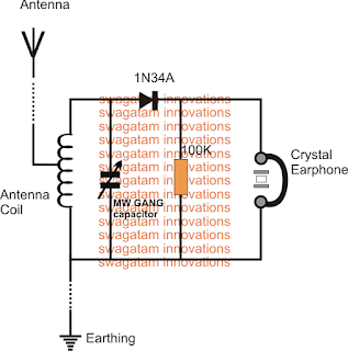
The main components involved with this simple crystal radio set circuit are an ordinary antenna coil, a detector diode, an optional resistor, and a crystal earphone. The detector diode could be any regular germanium diode such as OA91 or 1N34A etc.
A crystal earphone is recommended here, due to its high impedance property, which makes it a voltage sensitive device rather than a current sensitive device.
Meaning the earphone would be able to transform even the weakest of voltage frequencies regardless of the current (mA) magnitude, enabling hearing of even the feeblest of the radio signals. This is crucial since no external power is being used for the amplification.
Typically a crystal earphone with a range of 2K ohms should be just good enough value for our crystal radio application.
To check the efficiency level of a crystal earphone, you could probably do a few simple but very interesting tests with it.
The first test could be performed by simply scratching the end terminals of its wires with each other, this should produce faint clicking sound in the earphone, another test can be tried by firmly holding the stripped ends of its wires and standing near your home mains line....this should enable you to hear a reasonably strong humming sound in the earphone. These tests might be enough to convince you regarding the high level of sensitivity that these units may be specified with.
This high sensitivity of the crystal earphone along with the resonant tuning of the radios LC tank circuit stage, together ensures a sound level thats loud enough to be clearly heard without using any form of external power supply.
With no external power, the weak electrical pulses of the radio signal is itself processed and used by the crystal circuit and the crystal earphone and is made efficiently audible in our ears.
This radio can be used for hearing local stations at around 50kms range during daytime and from over 100 of miles away at night when the surrounding noise is much reduced compared to the daytime commotion.
The key element that helps the crystal set to grab even the minutest of radio reception is the length of the antenna used, it should be preferably a 30to 40 meter long flexible wire suitably tied and hung at some elevation such as a tree branch etc.
The antenna will be capable of capturing quite many radio stations including the night time DX stations, due to the favorable ionosphere transition after the sun goes down.
The second crucial element of the design is the "earthing" or the ground quality, which should not be ignored otherwise the radio could simply refuse to provide the intended results.
A perfect ground can be achieved by inserting a steel rod deep into a 5 feet hole dug on earth which should be first adequately watered to make it soft and then a bag of salt thrown into it to make things sufficiently conductive, and for creating an efficient grounding for the circuit.
Another easy method for achieving the earthing is by using the tap or the metallic plumbing line of your bathroom which also would act as a very good earthing for the circuit.
Circuit Description
Once the above mentioned antenna and the earthing is correctly set up, its time to connect the simple crystal radio circuit with these parameters.
Referring to the figure above, we see that the circuit hardly comprises any serious parts, it uses one antenna coil made by winding many turns of thin copper wire over a plastic bobbin with three wire ends terminating outwards, wherein the mid tap is used for the antenna connection.
The resonant tank circuit is formed by connecting a trimmer parallel to the antenna coil ends, this trimmer could be any MW GANG capacitor, again the same could be salvaged from any old radio set.
The radio signals are picked and resonated to the peak level through this tank circuit network, however in order to detect and demodulate the sound from the signals carrier waves we need another stage for this function.
An ordinary germanium diode is what we need to carry out the detection work and it does this quite effectively. Even our very familiar silicon 1N4148 could be tried for the job but only in case you are unable to procure the regular OA91 or the IN34A type of devices. And this part is the only active component involved in the whole circuit for reproducing the original sound from the captured signals, thats amazing.
How to Wind the Antenna Coil:
The antenna coil is an air cored winding, its built with the following simple steps:
You will need a 1 or 1.5 inch diameter, and 4 inches long plastic pipe for the bobbin.
Over this pipe wind some 65 turns of any thin super enameled copper wire or any thin insulated flexible wire such as a 7/36 multi strand insulated wire.
Make sure to pull out a center tap at around 18th turn of the winding, or some other number tap can also experimented with for trying preferred customized receptions.
Thats all, the antenna coil is ready and may be used for the above explained simple crystal radio circuit.
If you have any questions or doubts, dont hesitate to put it forth through comments below
The only downside of this radio concept is the requirement of a very long antenna and a deep earthing, therefore this unit is not something which you can carry in your pocket, nevertheless the extreme simplicity and the no power operation feature make this circuit an amazing device.
The main components involved with this simple crystal radio set circuit are an ordinary antenna coil, a detector diode, an optional resistor, and a crystal earphone. The detector diode could be any regular germanium diode such as OA91 or 1N34A etc.
A crystal earphone is recommended here, due to its high impedance property, which makes it a voltage sensitive device rather than a current sensitive device.
Meaning the earphone would be able to transform even the weakest of voltage frequencies regardless of the current (mA) magnitude, enabling hearing of even the feeblest of the radio signals. This is crucial since no external power is being used for the amplification.
Typically a crystal earphone with a range of 2K ohms should be just good enough value for our crystal radio application.
To check the efficiency level of a crystal earphone, you could probably do a few simple but very interesting tests with it.
The first test could be performed by simply scratching the end terminals of its wires with each other, this should produce faint clicking sound in the earphone, another test can be tried by firmly holding the stripped ends of its wires and standing near your home mains line....this should enable you to hear a reasonably strong humming sound in the earphone. These tests might be enough to convince you regarding the high level of sensitivity that these units may be specified with.
This high sensitivity of the crystal earphone along with the resonant tuning of the radios LC tank circuit stage, together ensures a sound level thats loud enough to be clearly heard without using any form of external power supply.
With no external power, the weak electrical pulses of the radio signal is itself processed and used by the crystal circuit and the crystal earphone and is made efficiently audible in our ears.
This radio can be used for hearing local stations at around 50kms range during daytime and from over 100 of miles away at night when the surrounding noise is much reduced compared to the daytime commotion.
The key element that helps the crystal set to grab even the minutest of radio reception is the length of the antenna used, it should be preferably a 30to 40 meter long flexible wire suitably tied and hung at some elevation such as a tree branch etc.
The antenna will be capable of capturing quite many radio stations including the night time DX stations, due to the favorable ionosphere transition after the sun goes down.
The second crucial element of the design is the "earthing" or the ground quality, which should not be ignored otherwise the radio could simply refuse to provide the intended results.
A perfect ground can be achieved by inserting a steel rod deep into a 5 feet hole dug on earth which should be first adequately watered to make it soft and then a bag of salt thrown into it to make things sufficiently conductive, and for creating an efficient grounding for the circuit.
Another easy method for achieving the earthing is by using the tap or the metallic plumbing line of your bathroom which also would act as a very good earthing for the circuit.
Circuit Description
Once the above mentioned antenna and the earthing is correctly set up, its time to connect the simple crystal radio circuit with these parameters.
Referring to the figure above, we see that the circuit hardly comprises any serious parts, it uses one antenna coil made by winding many turns of thin copper wire over a plastic bobbin with three wire ends terminating outwards, wherein the mid tap is used for the antenna connection.
The resonant tank circuit is formed by connecting a trimmer parallel to the antenna coil ends, this trimmer could be any MW GANG capacitor, again the same could be salvaged from any old radio set.
The radio signals are picked and resonated to the peak level through this tank circuit network, however in order to detect and demodulate the sound from the signals carrier waves we need another stage for this function.
An ordinary germanium diode is what we need to carry out the detection work and it does this quite effectively. Even our very familiar silicon 1N4148 could be tried for the job but only in case you are unable to procure the regular OA91 or the IN34A type of devices. And this part is the only active component involved in the whole circuit for reproducing the original sound from the captured signals, thats amazing.
How to Wind the Antenna Coil:
The antenna coil is an air cored winding, its built with the following simple steps:
You will need a 1 or 1.5 inch diameter, and 4 inches long plastic pipe for the bobbin.
Over this pipe wind some 65 turns of any thin super enameled copper wire or any thin insulated flexible wire such as a 7/36 multi strand insulated wire.
Make sure to pull out a center tap at around 18th turn of the winding, or some other number tap can also experimented with for trying preferred customized receptions.
Thats all, the antenna coil is ready and may be used for the above explained simple crystal radio circuit.
If you have any questions or doubts, dont hesitate to put it forth through comments below
Available link for download
Subscribe to:
Posts (Atom)