Tuesday, August 30, 2016
Triac SPDT Relay Circuit
Triac SPDT Relay Circuit
The post details a simple solid state triac SPDT relay circuit, using an optocoupler and a couple of triacs, which can be used as an effective replacement for mechanical relays. The idea was requested by "Cypherbuster".
In one of the other posts we learned how to make an DPDT SSR using mosfets, however this design could be used only for high current DC loads, and not with AC loads at the mains level.
In this article we will see how a simple mains operated solid-state relay can be made using triacs and an optocoupler.
The following figure show the details of the design:
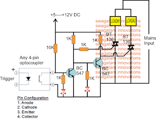
The working of any relay is specifically intended to operate two different high power loads individually and alternately with the help of an external isolated low power trigger.
In a conventional mechanical type of rely this is done by toggling the loads across its N/O and N/C contacts in response to the activation applied across its coil.
However mechanical relays have their own drawbacks such as higher degree of wear and tear, lower life, generation of RF disturbance due to sparks across the contacts, and the most vital being the delayed switching response which could be crucial in systems like UPS.
In our triac SPDT relay circuit the same function is executed through the switching of two triacs via two BJT stages and an isolating optocoupler which ensures that the changeover operation for this relay has no drawbacks as mentioned above.
Referring to the diagram, the left side triac represents the N/O contact while the right side triac operates like the N/C contact.
While the optocoupler is in the non-triggered mode, the BC547 directly associated with the opto goes into the triggered mode, which keeps the second BC547 switched OFF. This situation enables the right side triac to remain switched ON, and the other triac is held switched OFF.
In this condition any load connected with the right triac becomes operational and stays switched ON.
Now as soon as a trigger is applied to the opto coupler, it switches ON, and in turn switches OFF the connected BC547.
This situation switches ON the second BC547 and consequently the right side triac is switched OFF, ensuring that the left side triac is now switched ON.
The above condition immediately toggles the second load ON and switches OFF the earlier load, effectively fulfilling the required alternate switching of the load with the help of an isolated external DC trigger.
The two LED connected with the bases of the two BJTs indicate which load is in the activated state at any moment while the triac SPDT relay circuit is being operated.
The above design could be further enhanced and made fully independent of an external DC power source by upgrading it with its own transformerless power supply, as shown below:

In one of the other posts we learned how to make an DPDT SSR using mosfets, however this design could be used only for high current DC loads, and not with AC loads at the mains level.
In this article we will see how a simple mains operated solid-state relay can be made using triacs and an optocoupler.
The following figure show the details of the design:
The working of any relay is specifically intended to operate two different high power loads individually and alternately with the help of an external isolated low power trigger.
In a conventional mechanical type of rely this is done by toggling the loads across its N/O and N/C contacts in response to the activation applied across its coil.
However mechanical relays have their own drawbacks such as higher degree of wear and tear, lower life, generation of RF disturbance due to sparks across the contacts, and the most vital being the delayed switching response which could be crucial in systems like UPS.
In our triac SPDT relay circuit the same function is executed through the switching of two triacs via two BJT stages and an isolating optocoupler which ensures that the changeover operation for this relay has no drawbacks as mentioned above.
Referring to the diagram, the left side triac represents the N/O contact while the right side triac operates like the N/C contact.
While the optocoupler is in the non-triggered mode, the BC547 directly associated with the opto goes into the triggered mode, which keeps the second BC547 switched OFF. This situation enables the right side triac to remain switched ON, and the other triac is held switched OFF.
In this condition any load connected with the right triac becomes operational and stays switched ON.
Now as soon as a trigger is applied to the opto coupler, it switches ON, and in turn switches OFF the connected BC547.
This situation switches ON the second BC547 and consequently the right side triac is switched OFF, ensuring that the left side triac is now switched ON.
The above condition immediately toggles the second load ON and switches OFF the earlier load, effectively fulfilling the required alternate switching of the load with the help of an isolated external DC trigger.
The two LED connected with the bases of the two BJTs indicate which load is in the activated state at any moment while the triac SPDT relay circuit is being operated.
The above design could be further enhanced and made fully independent of an external DC power source by upgrading it with its own transformerless power supply, as shown below:
Available link for download